Quantcast
Channel: Arduino Basics
Viewing all 112 articles
Browse latest View live

Relay Module

$
0
0

WARNING: Mishandling or incorrect or improper use of relays could result in

  • serious personal injury or DEATH
  • possible physical damage of the product
  • faulty operation
  • or create serious/dangerous hazards.

Please make sure that you read and understand how your relay/relay module board works, the voltage and current it is rated for, and the risks involved in your project BEFORE you even attempt to start putting it together. Seek professional and qualified assistance BEFORE you undertake ANY high power projects.

If you choose to follow the instructions in this tutorial, you do so at your own risk. I am not an electrician, and am not a qualified electrical engineer - so please do your research and seek advice BEFORE undertaking a project using a relay. Please check your connections and test them BEFORE turning the power on.

I accept no responsibility for your project, or the risk/damage/fire/shock/injury/death/loss that it causes. You take full responsibility for your actions/project/creation, and do so at YOUR OWN RISK !!!

Please note: It is illegal in some countries to wire up a high power project without an electrician. Please check your country's rules/laws/regulations before you undertake your project. If you have any doubts - don't do it.


&nbsp

What is a relay

A Relay is an electrically operated switch. Many relays use an electromagnet to mechanically operate the switch and provide electrical isolation between two circuits. In this project there is no real need to isolate one circuit from the other, but we will use an Arduino UNO to control the relay. We will develop a simple circuit to demonstrate and distinguish between the NO (Normally open) and NC (Normally closed) terminals of the relay. We will then use the information gained in this tutorial to make a much more exciting circuit. But we have to start somewhere. So let's get on with it.

Parts Required:

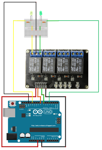
Fritzing Sketch


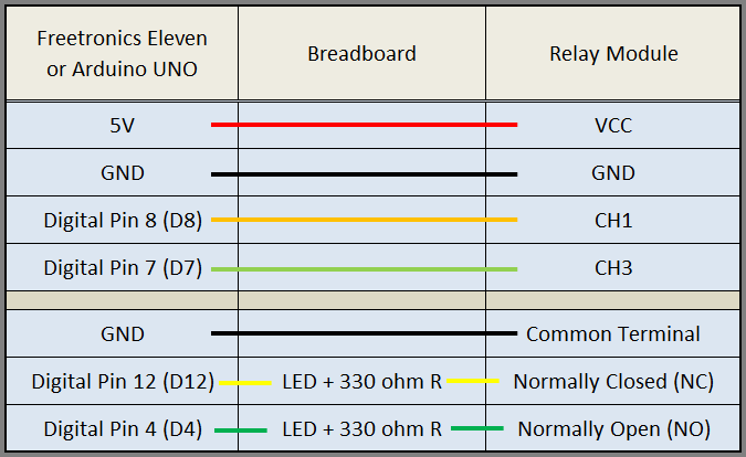
Table of Connections


Arduino Sketch


  1
2
3
4
5
6
7
8
9
10
11
12
13
14
15
16
17
18
19
20
21
22
23
24
25
26
27
28
29
30
31
32
33
34
35
36
37
38
39
40
41
42
43
44
45
46


/* ===============================================================
      Project: 4 Channel 5V Relay Module
       Author: Scott C
      Created: 7th Sept 2014
  Arduino IDE: 1.0.5
      Website: http://arduinobasics.blogspot.com.au
  Description: Explore the difference between NC and NO terminals.
================================================================== */

 /*
  Connect 5V on Arduino to VCC on Relay Module
  Connect GND on Arduino to GND on Relay Module 
  Connect GND on Arduino to the Common Terminal (middle terminal) on Relay Module. */
 
 #define CH1 8   // Connect Digital Pin 8 on Arduino to CH1 on Relay Module
 #define CH3 7   // Connect Digital Pin 7 on Arduino to CH3 on Relay Module
 #define LEDgreen 4 //Connect Digital Pin 4 on Arduino to Green LED (+ 330 ohm resistor) and then to "NO" terminal on relay module
 #define LEDyellow 12 //Connect Digital Pin 12 on Arduino to Yellow LED (+ 330 ohm resistor) and then to "NC" terminal on relay module
 
 voidsetup(){
   //Setup all the Arduino Pins
   pinMode(CH1, OUTPUT);
   pinMode(CH3, OUTPUT);
   pinMode(LEDgreen, OUTPUT);
   pinMode(LEDyellow, OUTPUT);
   
   //Provide power to both LEDs
   digitalWrite(LEDgreen, HIGH);
   digitalWrite(LEDyellow, HIGH);
   
   //Turn OFF any power to the Relay channels
   digitalWrite(CH1,LOW);
   digitalWrite(CH3,LOW);
   delay(2000); //Wait 2 seconds before starting sequence
 }
 
 voidloop(){
   digitalWrite(CH1, HIGH); //Green LED on, Yellow LED off
   delay(1000);
   digitalWrite(CH1, LOW); //Yellow LED on, Green LED off
   delay(1000);
   digitalWrite(CH3, HIGH); //Relay 3 switches to NO
   delay(1000);
   digitalWrite(CH3,LOW); //Relay 3 switches to NC
   delay(1000);
 }


The Red light on the Relay board turns on when power is applied (via the VCC pin). When power is applied to one of the Channel pins, the respective green light goes on, plus the relevant relay will switch from NC to NO. When power is removed from the channel pin, the relay will switch back to NC from NO. In this sketch we see that power is applied to both LEDs in the setup() method. When there is no power applied to the CH1 pin, the yellow LED will be on, and the Green LED will be off. This is because there is a break in the circuit for the green LED. When power is applied to CH1, the relay switches from NC to NO, thus closing the circuit for the green LED and opening the circuit for the yellow LED. The green LED turns on, and the yellow LED turns off.

I also show what happens when you apply power to a channel (eg. CH3) when there is nothing connected to the relay terminals. The respective onboard LED illuminates. This is useful for troubleshooting the relays, and knowing what state the relay is in (NC or NO). NC stands for Normally closed (or normally connected) NO stands for Normally open (or normally disconnected)

Here is a circuit diagram for two of the relays on the relay module (CH1 and CH2).
This was taken from the iteadstudio site.


The Video


This tutorial will become very useful in the future. I now have an easy way of switching a circuit electronically. Yes, I could do this with a transistor, but sometimes it is nice to hear that mechanical click. I am not sure why I like relays, but I find them to be quite fun !!

If you liked this tutorial - please show your support :


Arduino based Security Project Using Cayenne

$
0
0


Description

This is an Arduino based home security project that uses the power of "Cayenne" for extraordinary capabilities.

Cayenne Beta

Cayenne is a new IoT drag and drop platform originally released for the Raspberry Pi, but now available for Arduino. Cayenne makes the task of connecting your Arduino to the internet as simple as possible. All of the complexity of internet connectivity is hidden within the Cayenne library.

You can easily create a Network of Arduinos and build an IoT system which can be managed and operated within the Cayenne dashboard. This dashboard is accessible through your browser or via the Cayenne smart phone app (on IOS or Android).

The feature I liked the most, was the ability to change the position of sensors or actuators on the Arduino without having to re-upload Arduino code. I could manage the changed position from within the Cayenne platform. The other feature that I liked was the ability to setup actions based on custom triggers. You can use Cayenne to trigger a whole range of functions, for example: play a sound, move a motor, light up an LED, or to send alert notifications via email or SMS.

Cayenne is in Beta at the moment, so there are a few minor bugs here and there, but overall - I give it a thumbs up - it is definitely worth checking out.
 

Here is a link to the Cayenne Beta Program:
**Cayenne Beta Link**


              Source: myDevices Media Kit  

Home Security Project Summary

In order to fully experience this new IoT platform, I decided to create a project to really put it through its paces. This is what my Security Project will need:

  1. It will use two Arduinos, one connected to the internet via an Ethernet shield, and the other via WIFI.
  2. Two detectors - a PIR sensor and a laser trip wire.
  3. If the sensors are tripped, the person has 10 seconds to present an RFID tag to the Grove RFID reader:
    • If a valid RFID tag is SUCCESSFULLY presented within the time limit, a nice personalised greeting will be played to that person using a Grove - Serial MP3 player
    • If a valid RFID FAILS to be presented within the time limit, an Alarm will sound, and I will be notified of the intrusion via an SMS alert.
  4. The Cayenne dashboard will show the status of the sensors, and I will have full control over my security system via the web interface (or smartphone app).
  5. The sensors will be attached to a different Arduino to that of the Grove MP3 player and the RFID tag reader, which means that there will have to be some level of communication between the two Arduinos. In fact, the cross communication will be vital to the success of this project.


Project Video


Flow Diagrams:

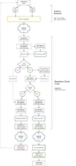
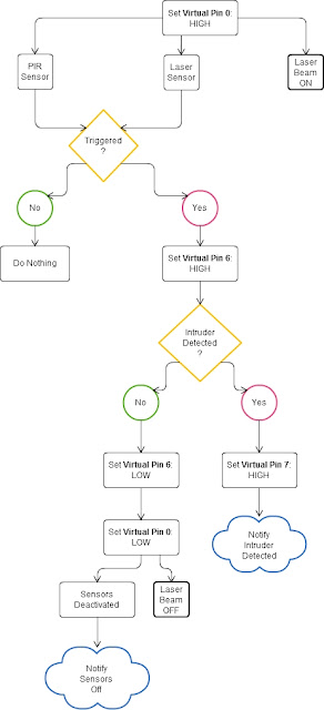
Main Flow Diagram

The following flow diagram shows the Security project process. It is a high level view of the decisions being made by each Arduino in response to various events.  


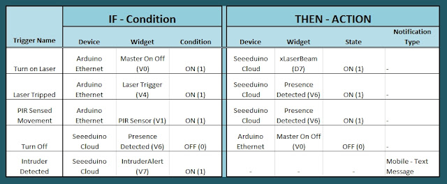
Triggers Flow Diagram

The following flow diagram aims to highlight the various triggers set up within Cayenne to get this Security system to work.  


Arduino IDE and Library Downloads

You will need an Arduino IDE to upload code to the Arduino and the Seeeduino Cloud.
Here is the link to the Arduino IDE: Arduino IDE - download location

The Cayenne service requires that you download and install the Cayenne Library into your Arduino IDE.
You can get the Cayenne Library from here: Cayenne Library File - Download


Cayenne Connectivity Setup

The Seeeduino Cloud needs to be prepared for use with Cayenne.
Normal operating/setup instructions can be found here: Seeeduino Cloud WIKI page
 
Once you have successfully connected Seeeduino Cloud to your WIFI network, you can add it to the Cayenne Dashboard by making the following selections from within the Cayenne Web application:

  1. Add New
  2. Device/Widget
  3. Microcontrollers
  4. Arduino
  5. Ensure Seeeduino Cloud is connected to WIFI network - the select the NEXT button
  6. Select - Arduino Yun: Built-in Ethernet - ticked
  7. Providing you have already installed the Cayenne library as described above - you should be able to copy and paste the code to the Arduino IDE and upload to the Seeeduino Cloud.
  8. If successful, you should see the Arduino Yun board appear within the Cayenne Dashboard. If not, then seek help within the Cayenne forum.


The Arduino UNO with WIZNET 5100 - Ethernet Shield
also needs to be prepared with Cayenne

  1. Add New
  2. Device/Widget
  3. Microcontrollers
  4. Arduino
  5. Ensure Arduino is powered, and Ethernet shield is connected to your internet router via an Ethernet cable
  6. Select - Arduino Uno: Ethernet Shield W5100 - ticked
  7. Copy and paste the code to the Arduino IDE and upload to the Arduino UNO.
  8. If successful, you should see the Arduino Uno board appear within the Cayenne Dashboard. If not, then seek help within the Cayenne forum.


If you have the Ethernet shield with the WIZNET 5200 chip, then you may need to download a specific Ethernet library in addition to the Cayenne library.
 
Just follow the instructions within the Automatically generated sketch provided - when you select your specific Arduino/Ethernet/WIFI shield combination. If you need further instructions on connecting your device to Cayenne - then please visit the myDevices website for the online documentation.


ARDUINO CODE (1)


Code for Arduino UNO with Ethernet Shield:

The following code will need to be uploaded to the Arduino UNO:


ARDUINO CODE (2)


Code for Seeeduino Cloud:

The following code will need to be uploaded to the Seeeduino Cloud:


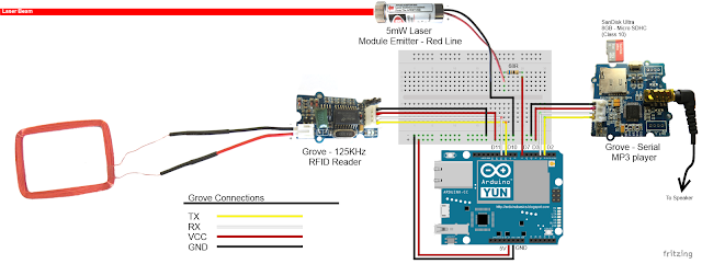
Fritzing diagram (1)


Fritzing diagram for Arduino UNO with Ethernet

Please click on the picture below for an enlarged version of this fritzing diagram


Fritzing diagram (2)


Fritzing diagram for Seeeduino Cloud

Please click on the picture below for an enlarged version of this fritzing diagram


Cayenne Dashboard Setup - GUI


The Arduino code only provides half of the functionality of this project. The Cayenne Dashboard needs to be setup to provide the rest of the functionality. The following instructions will show you how to add each of the widgets required for this Home Security project.

Arduino Ethernet - Master Switch

The master switch allows me to turn the security system on and off. When I turn the MASTER SWITCH ON, the laser beam will turn on, and the sensors will start monitoring the area for intruders. This widget is NOT associated with a physical switch/sensor on the Arduino - it uses virtual channel 0. We need to add the Master switch to the dashboard:


  1. Add New
  2. Device/Widget
  3. Actuators
  4. Generic
  5. Digital Output - Control a Digital Output
  6. Widget Name: Master On Off Switch
  7. Select Device: Arduino Ethernet
  8. Connectivity: Virtual
  9. Pin: V0
  10. Choose Widget: Button
  11. Choose Icon: Valve
  12. Step2: Add Actuator
We will add a trigger later to get this button to automatically turn the Laser beam on.


Arduino Ethernet - PIR Sensor

This sensor will be used to detect movement in the room. If a person walks into the room, this sensor will detect movement, and will trigger a message to be played on the Grove Serial MP3 player. The message will aim to get the person to identify themselves. They identify themselves by placing their RFID tag in close proximity to the Grove RFID reader. If the tag is valid, a "Welcome home" message is played on the Grove MP3 player. If a valid tag is not presented to the reader within 10 seconds, an Alarm will go off ("Alarm sound" played on Grove MP3 player.)

The PIR sensor is connected to digital Pin 6 of the Arduino, however, it is mapped to virtual pin 1 for better synchronisation with the Cayenne dashboard. This was done to capture ALL detections - as the PIR sensor could change from a LOW to HIGH and back to LOW state in between a Cayenne state check - and therefore, Cayenne could miss this motion detection.. Therefore we need to assign the PIR sensor to a virtual channel in the following way:
  1. Add New
  2. Device/Widget
  3. Sensors
  4. Motion
  5. Digital Motion Sensor - Motion Detector
  6. Widget Name: PIR sensor
  7. Select Device: Arduino Ethernet
  8. Connectivity: Virtual
  9. Pin: V1
  10. Choose Widget: 2-State Display
  11. Choose Icon: Light
  12. Step2: Add Sensor
  13. Select Settings from the PhotoResistor
  14. Choose Display: Value
  15. Save


Arduino Ethernet - Photoresistor

This sensor will be used with the laser beam to create a laser tripwire. If the sensor detects a change in light levels (drops below the threshold), it will activate the laser trigger button on the dashboard. The person will then be required to identify themselves etc etc (similar to the motion detection by the PIR sensor). The photoresistor widget will display the raw analog reading from the sensor (connected to A2), but is associated with virtual channel 2. I used a virtual channel for more control over this sensor. To add the Photoresistor to the dashboard:

  1. Add New
  2. Device/Widget
  3. Sensors
  4. Luminosity
  5. Photoresistor - Luminosity sensor
  6. Widget Name: PhotoResistor
  7. Select Device: Arduino Ethernet
  8. Connectivity: Virtual
  9. Pin: V2
  10. Choose Widget: Value
  11. Choose Icon: Light
  12. Step2: Add Sensor


Arduino Ethernet - Laser Trigger

The laser trigger is just an indicator that someone tripped the laser beam. The state of this widget is used to notify the Seeeduino that a presence has been detected. This widget is associated with virtual pin 4 on the Arduino UNO with Ethernet.

  1. Add New
  2. Device/Widget
  3. Actuators
  4. Generic
  5. Digital Output - Control a Digital Output
  6. Widget Name: Laser Trigger
  7. Select Device: Arduino Ethernet
  8. Connectivity: Virtual
  9. Pin: V4
  10. Choose Widget: Button
  11. Choose Icon: Lock
  12. Step2: Add Actuator


Arduino Ethernet - Laser Threshold

The laser threshold is used to manually configure the light level at which the laser trigger will trip. When the photoresistor value drops below the threshold value, the laser trigger icon will activate. This allows the threshold value to be updated from the Cayenne dashboard, rather than having to manually adjust the value in the Arduino code. Also, this threshold can be set remotely, in that you don't have to be near the Arduino to change this value. A very useful feature of this Security system. This widget is associated with virtual pin 5 on the Arduino UNO with Ethernet.

  1. Add New
  2. Device/Widget
  3. Actuators
  4. Generic
  5. PWM Output - Control a PWM Output
  6. Widget Name: Laser Threshold
  7. Select Device: Arduino Ethernet
  8. Connectivity: Virtual
  9. Pin: V5
  10. Choose Widget: Slider
  11. Slider Min Value: 0
  12. Slider Max Value: 10
  13. Step2: Add Actuator
The max value of the slider is 10 - due to a current bug in the Cayenne software. Once resolved, this value (as well as the relevant Arduino code) will need to be updated.


Seeeduino Cloud - Presence Detected

The presence detected widget is there to notify the Seeeduino Cloud that a presence has been detected on the Arduino Uno with Ethernet shield. When the PIR sensor detects movement or if the laser tripwire is tripped, Cayenne will change the state of the Presence Detected widget from LOW to HIGH. This is used within the Seeeduino Cloud to trigger the message "Place your keys on the Mat"
. If a valid RFID tag is read by the Grove RFID reader, then this widget's state will change back from HIGH to LOW, and the MasterSwitch will be deactivated - turning the Security system off. This widget is associated with Virtual pin 6 on the Seeeduino Cloud.

  1. Add New
  2. Device/Widget
  3. Actuators
  4. Generic
  5. Digital Output - Control a Digital Output
  6. Widget Name: Presence Detected
  7. Select Device: Seeeduino Cloud
  8. Connectivity: Virtual
  9. Pin: V6
  10. Choose Widget: Button
  11. Choose Icon: Lock
  12. Step2: Add Actuator


Seeeduino Cloud - Intruder Alert

If a valid RFID tag is not read by the Grove RFID reader within 10 seconds of a presence detection event, an alarm will sound, and this widget will be activated. This will trigger a notification event - to notify me of the unauthorised intrusion - via SMS or email. I will also have a visual indicator on the Cayenne dashboard that an intrusion has taken place. This widget is associated with Virtual pin 7 on the Seeeduino Cloud.

  1. Add New
  2. Device/Widget
  3. Actuators
  4. Generic
  5. Digital Output - Control a Digital Output
  6. Widget Name: Laser Trigger
  7. Select Device: Seeeduino Cloud
  8. Connectivity: Virtual
  9. Pin: V7
  10. Choose Widget: Button
  11. Choose Icon: Thermometer
  12. Step2: Add Actuator


Seeeduino Cloud - Laser Beam

The laser beam widget was created to allow for full control over the laser beam. The laser beam can be turned on or off from the Cayenne dashboard, and a connected to digital pin 7 on the Seeeduino Cloud.


  1. Add New
  2. Device/Widget
  3. Actuators
  4. Light
  5. Light Switch - Turn On/Off a Light
  6. Widget Name: xLaser Beam
  7. Select Device: Seeeduino Cloud
  8. Connectivity: Digital
  9. Pin: D7
  10. Choose Widget: Button
  11. Choose Icon: Light
  12. Step2: Add Actuator


Cayenne Triggers

Now that all of the widgets have been added to the Dashboard, there is just one more step to complete the Security System. We need to setup the triggers. These triggers provide a level of automation that is easy to create within Cayenne, but would be very complicated otherwise. I set my triggers up as per the table below. Each row represents one of the triggers within my Cayenne dashboard. If you would like to see an example of how to add a trigger - please have a look at the video at the top of this tutorial.  


Concluding comments

I used many different elements to put this home/office security project together - Multiple Arduinos were connected to the internet, both controlled by a web/smart phone app, cross-communication/synchronisation between the Arduinos, and the use of multiple sensors and modules including a laser beam !
 
This was way more than just a simple PIR sense and alarm project. I now have a personalised greeting and reminder system when I walk in the door. Everyone else has their own personalised greeting. I can enable my Security System remotely, from two blocks away, and if I wanted to - I could enable it from the other side of the world. I know instantly when someone has entered my house/office.... with an SMS alert straight to my phone.
 
This project could easily be extended:

  1. Press a button on my phone to manually trigger/play a specific message/sound/song
  2. Take a picture of the intruder
  3. Introduce fire or leak detection aswell
  4. Add other environmental sensors - Temperature / Humidity
  5. Connect it to lamp/light - creating a security light
I am sure you can think of more things I could do with this system. In fact, why don't you mention your ideas in the comments below.
 
Cayenne was instrumental in getting this project to work. I don't think I would know where to start if I had to do this project without this cool IoT platform. I think I will definitely be trying out a few more projects using Cayenne, and should you want to do the same, then please make sure to join Cayenne Beta:
 
Here is the link you need to get to the right place: Cayenne Beta Link

 
If you like this page, please do me a favour and show your appreciation :

 
Visit my ArduinoBasics Google + page.
Follow me on Twitter by looking for ScottC @ArduinoBasics.
I can also be found on Pinterest and Instagram.
Have a look at my videos on my YouTube channel.

EasyEDA RGB5050 LED Scroll Bar

$
0
0


Guest Post Disclaimer

This is a guest post by the EasyEDA team. I would like to thank EasyEDA for providing this tutorial for everyone to enjoy. All information within this post was provided by EasyEDA.


Description

None of us could deny the fact that we would love with to play with LED’s and lighting stuff. I love to play with LED’s and create attractive lighting effects. This project was a result of such an attempt where I created a stunning RGB light effect using the popular development platform Arduino Nano. Let’s see the circuit, code and instruction on building this project:


Image source: EasyEDA


Arduino Libraries and IDE

No libraries are required for this project. The Arduino IDE can be downloaded from the Arduino website. Here is the download link.

ARDUINO CODE:


Preparing the LED strips

Cut down the LED strips into 10 single pieces. Make sure you cut them into equal halves and make sure that only the copper conduction plate in the strip is cut. Making a wrong cut disrupts the electrical conductivity between the LED’s. After cutting down into separate strips, you will need to connect each strip using a Dupont wire connectors.

Image source: EasyEDA


Designing the Control Board

I have made a custom control board that incorporates an Arduino Nano. The control board is used to boost the incoming signal from Arduino and lights up the corresponding LED strips.


Image source: EasyEDA


Control Board Circuit diagram

I used a free Online circuit and PCB designing platform called EasyEDA to develop my control board. It is pretty easy to use especially because of the large library of parts to choose from. Once the design is complete, you have the option to order it through EasyEDA. They offers great prices on custom PCB manufacturing. I have added 10 connection points for 10 LED strips. Each RGB LED strip is controlled by one of the Arduino Nano digital pins.. Transistors Q1,Q2,Q3….Q10 act as a switch for these LED strips for controlling 12V strips via a 5V signal from the Arduino. And switches S1,S2..S4 were added to be able to select the effect on the strip. The schematic can be seen below:


Schematic

You can access the actual EasyEDA schematic by clicking on the image below:

Image source: EasyEDA


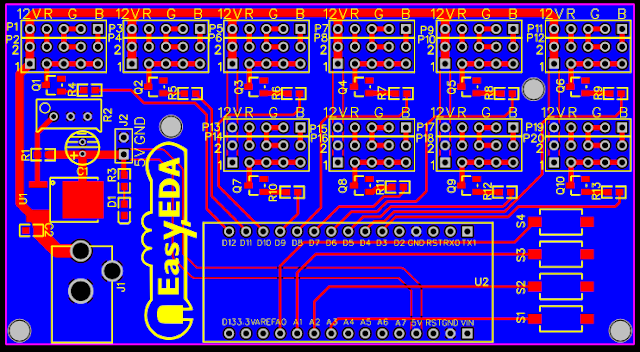
PCB Board Design

Here is the PCB board design for this project.
You can access the actual EasyEDA design by clicking on the image below.

Image source: EasyEDA


PCB Fabrication

After completing the PCB design, you can click on the Fabrication icon.

You will then have access to the PCB order page which will allow you to download your PCB Gerber files that can be sent to any manufacturer. However it is a lot easier (and cheaper) to order it directly from EasyEDA.
Here you can select:

  • the number of PCBs you want to order
  • the number of copper layers you need
  • the PCB thickness
  • copper weight
  • and even the PCB color
After you’ve selected all of the options, click “Save to Cart” and complete you order. You will then get your PCBs shipped a few days later.

Image source: EasyEDA


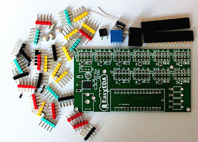
PCB final product

When I received the PCBs, I am quite impressed with the quality, they are pretty nice.

Image source: EasyEDA


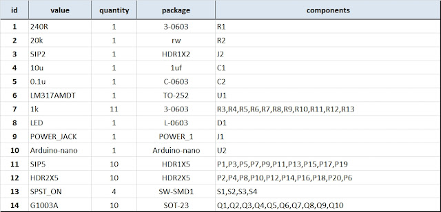
PCB Build of Materials

Image source: EasyEDA


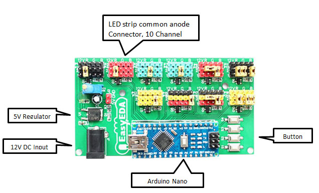
PCB connections

Connect the LED strips through the connection points in the board. Make sure that you connect these correctly (push the connectors all the way onto the pin), because the chances of a short increase significantly with the number of wires connected. Once all the connections are done all that left is to install your Arduino Nano (pre-programmed with the Arduino code above), and to power the PCB with a 12V power supply.


Image source: EasyEDA


Project Video


Concluding comments

Hope you like this RGB light effects project, do try it out and post your feedback below.
 
Disclaimer:
This is a guest blog post by the EasyEDA team. All information within this post was provided by EasyEDA.

EspoTek Labrador Review

$
0
0
Have you heard about the EspoTek Labrador ? 

A tiny board which can turn your computer into an
- Oscilloscope
- Waveform generator
- Logic analyser
- Multimeter
- and Power supply.

Great for makers or hobbyists with limited bench space or limited funds. Perfect for students and anyone starting out in the field of electronics

As you will see in the video below, I take a prototype of the EspoTek Labrador for a spin, and try out all of the functions that this board can provide.

I use an Arduino UNO, a couple of 433MHz RF modules, some LEDs and a speaker to see just how useful this board will be for my hobby requirements.

I have been wanting an Oscilloscope for quite some time, and while this board does not necessarily win against a benchtop oscilloscope on a side-by-side comparison of specifications, it does make up for it somewhat in terms of price, space (or footprint), usability, and wide range of functionality. But does it actually function as an oscilliscope? Is it useful ? Will it do what I need it to do?  Or will I still need to buy that expensive oscilloscope that I have been saving up for?

Have a look at my review below, and tell me what you think.


Let me know your thoughts in the comments below:

HMC5883L on the GY-80 module

$
0
0

Description

In this tutorial, I will show you how to configure and extract data from the magnetometer (HMC5883L) sensor on the GY-80 10DOF module from ICStation. While there are some very good libraries on the internet which will give you full access to this sensor, I will show you what you need to know without using a library. This means that it may get a bit technical at times, but I will hold your hand along the way and provide explanations as required. I would also recommend that you watch the complete video from start to finish - as the video provides really useful information.


HMC5883L Magnetometer Datasheet:

You can find the datasheet for the HMC5883L pretty easily by searching on the internet. Here are a couple of sources:


Arduino Libraries

This tutorial does not use any external libraries.
It does use the Wire library for I2C communication.
However, there is no extra download required to access the Wire library.
If you are looking for a library specific for the HMC5883L sensor, then I would recommend one of these:

Like I said - you do not need an HMC5883L library for this tutorial. The libraries above are listed for those who wish to learn more about this particular sensor.

Arduino IDE

The Arduino IDE can be downloaded from the Arduino website. Visit the Arduino IDE download page.

I generally use the ZIP file for Windows and never seem to have any issues.
There are downloads available for all the major operating systems.


ARDUINO CODE:

I have created a Gist for the Arduino code to configure and extract data from the HMC5883L sensor. However, I also have a GitHub repository which aims to capture the code for all of the sensors on the GY-80 module. Code for the other sensors will become available in due time. Meanwhile, have a look at the code below for the HMC5883L sensor:

This code will set all axis values to 1000 upon startup. Moving the GY-80 module around will result in a value greater or less than 1000, however, returning the sensor back to it's original position, should result in values very close to 1000 on each axis. I chose to introduce this calibration in order to avoid negative values, and I liked the fact that I could set a heading with values that were easy to remember.
 
The magSetting function was created to easily configure the magnetometer.
Make sure to look at the video and also the datasheet for further information about calibrating the magnetometer.
 
The getReadings function was created to easily retrieve the magnetometer axis data. I chose to use Single measurement mode in this tutorial.


Hooking it up:

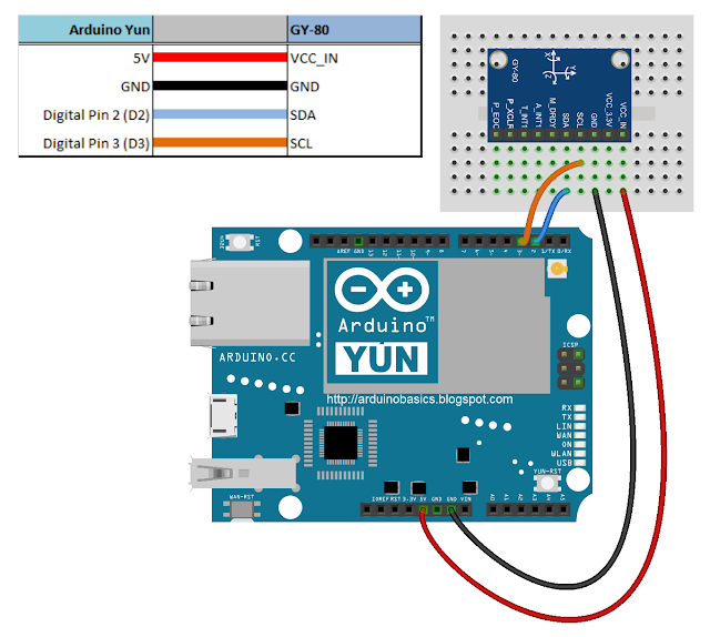
You can communicate with any of the sensors on the GY-80 module using I2C. The HMC5883L magnetometer sensor is no different. You will need four connections between the Arduino UNO and the GY-80 module. Have a look at the diagram below for the connection diagram and table.

Fritzing diagram


Project pictures


Concluding comments

The HMC5883L sensor on the GY-80 module is quite interesting and works relatively well. There are a number of other sensors on the GY-80 module which can provide complementary positional data. At some point, I plan to come back and explain some of the other sensors on this module, but first I would like to create a real-life project using the magnetometer. So stay tuned. You may want to subscribe to my social networks or to this blog to be notified of that project when I complete it.

I would like to thank ICStation for their collaborative efforts. Their contribution was invaluable to this tutorial's existence.

If you like this page, please do me a favour and show your appreciation :

 
Visit my ArduinoBasics Google + page.
Follow me on Twitter by looking for ScottC @ArduinoBasics.
I can also be found on Pinterest and Instagram.
Have a look at my videos on my YouTube channel.

Garage Door Monitor with Cayenne

$
0
0


Description

Using the HMC5883L magnetometer sensor of the GY-80 module from ICStation to monitor a garage door and notify when it has been opened or closed. The Cayenne service provides much of the monitoring and notifying functionality. A major feature of this project. Cayenne takes care of all of the complicated work behind the scenes, making it easy to connect your Arduino to the cloud and allow you to monitor your garage from virtually anywhere.
 
This project was created specifically to monitor a garage, but you will soon discover that this project could be used to monitor a whole host of other things. Monitor your front door, your back door, your bag, your chair, your cookie jar.
 
Monitor for peace of mind, or catch someone in the act of stealing your stuff. This project has got you covered. Let's see how:


HMC5883L DataSheet:

You can find the datasheet for the HMC5883L pretty easily by searching on the internet.
HMC5883L datasheet - Sparkfun


Arduino Libraries and IDE

Here is a link to the Arduino IDE download. The IDE is required to upload code to the Seeeduino Cloud.

You need the Cayenne Library installed in your Arduino IDE.
You can find the Cayenne library here:
Cayenne Libarary
 
There are libraries on the internet for the GY-80 module, however, it is relatively easy to use the magnetometer on this module. And therefore no libraries are required for the sensor. If you would like some more information about using the magnetometer sensor, and how to get the most out of it, then please have a look at my previous tutorial which goes into much more detail.


ARDUINO CODE:


You need to make sure to insert your OWN Cayenne token into the sketch above. You will get this token when connecting your Arduino to the Cayenne service. Watch the video for further explanation.


Fritzing diagram

Cayenne Widgets

Please make sure to watch the video to see how to connect the Seeeduino Cloud to Cayenne and how to create the Cayenne widgets. Cayenne widgets are necessary to create the dashboard on your phone or browser. They will also interact with the Arduino sketch, and will also be involved in creating the notification system. The following links will take you to the relevant part of the video:

The Master switch button is used to switch monitoring from OFF to ON (and vice versa). Therefore you can choose when to monitor the garage and when to stop monitoring. When first installing the project onto your garage door, and turning the Seeeduino Cloud on, it will automatically calibrate each sensor to a value of 1000.
 
If you experience any drift away from 1000 for whatever reason, simply press the Request calibration button, and each sensor will be recalibrated back to 1000. The x,y and z axis widgets are there so that you can see the readings coming from the magnetometer sensor. And when any of the axis variables breach the threshold away from 1000, it will trigger the Door Status widget. This is how we can tell if the door is open or closed.
 
We also use the Door Status widget to help with the notification system. When the Door status changes from "Closed" to "Open", a notification trigger will be activated, and a message will be sent via email or SMS. This notification is useful for monitoring when the door was opened. If you happen to recalibrate when the door is open. You will get a notification when the garage door closes.


Concluding comments

This project is relatively simple, and quite easy to set up. What I liked about this project was the versatility and alternate uses. You can use the same setup to monitor many different things. It is not just limited to monitoring a garage door. But being able to tell whether my garage door is opened or closed, especially after I have driven away from my house , is really cool. Now I don't have to drive all the way back home to check. Let me know if you have replicated this project, and also what kinds of things you decided to monitor with this project.

Prextron CHAIN BLOCKS - Arduino Nano controlled Ultrasonic sensor that switches a motor wirelessly using 433MHz RF modules and a relay board.

$
0
0


Description

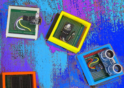
In this tutorial, I will be evaluating Prextron CHAIN blocks – a new system that allows you to connect your sensors and actuators to an Arduino NANO using clever 3D-printed prototyping boards that can be stacked sideways. This very modular system makes it easy to connect, disconnect and replace project components, and eliminate the “rats nest of wires” common to many advanced Arduino projects. CHAIN BLOCKS are open, which means that you can incorporate any of your sensors or actuators to these prototyping boards, and you can decide which specific pin on Arduino you plan to use. The CHAIN BLOCK connections prevent or reduce common connection mistakes, which make them ideal for class-room projects and learning activities.

I am going to set up a project to put these CHAIN BLOCKs to the test:
When I place my hand in-front of an Ultrasonic sensor, the Arduino will transmit a signal wirelessly to another Arduino, and consequently turn on a motor.


Parts Required:

You need the following Prextron Chain Blocks


Please note: You may need to solder the module wires to the CHAIN BLOCK protoboard.


Arduino Libraries and IDE

This project does not use any libraries. However, you will need to upload Arduino code to the Arduino. For this you will need the Arduino IDE which can be obtained from the official Arduino website:
https://www.arduino.cc/en/main/software


ARDUINO CODE: RF Transmitter


ARDUINO CODE: RF Receiver


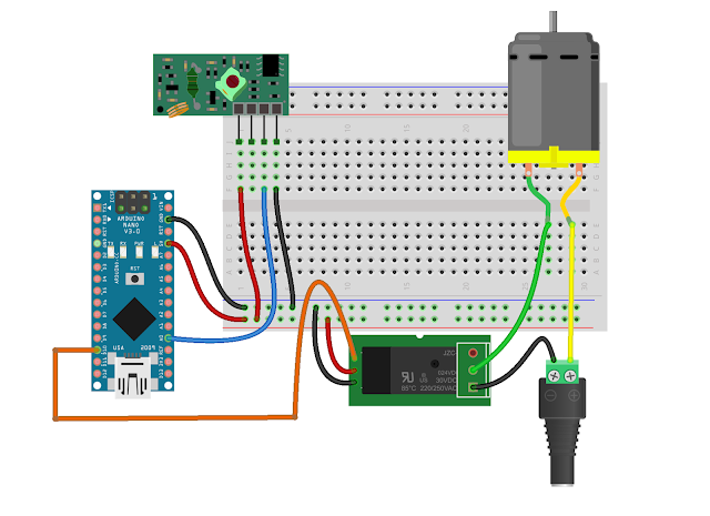
Fritzing diagrams for Transmitter


Fritzing diagrams for Receiver


Concluding comments

The purpose of this project was to evaluate Prextron CHAIN BLOCKs and put them to the test. Here is what I thought of CHAIN BLOCKS at the time of evaluation. Some of my points mentioned below may no longer apply to the current product. It may have evolved / improved since then. So please take that into consideration


What I liked about Chain Blocks

  • The design is simple, the product is simple.
  • Once the Chain Blocks were all assembled, they were very easy to connect to each other.
  • I can really see the benefit of Chain Blocks in a teaching environment, because it simplifies the connection process, and reduces connection mixups.
  • It was good to see that the blocks come in different colours, which means that you can set up different colour schemes for different types of modules.
  • You can incorporate pretty much any sensor or Actuator into the Chain block which is very appealing.
  • You also have the flexibility of choosing which pins you plan to use on the Arduino.
  • Projects look a lot neater, because you no longer have the rats nest of wires.
  • The Blocks lock into each other which means that they are much easier to transport/carry.


What I did not like about Chain Blocks

  • In most cases, the Chain Block protoboard lanes were not numbered, which increased the chances of making mistakes when soldering
  • The need to solder modules to the protoboard, may be a discouragement for some people.
  • I would have liked a choice of different size Chain blocks. Some of the sensors did not fit nicely into the Square blocks.
  • Prextron really need to work on their website if they plan to get serious with this product: Webpage has incomplete functionality or irrelevant links etc etc.


Thank you very much to Prextron for providing the CHAIN BLOCKS used in this tutorial, and allowing me to try out their product. If you are interested in trying them yourself, then make sure to visit them at:


If you like this page, please do me a favour and show your appreciation :

 
Visit my ArduinoBasics Google + page.
Follow me on Twitter by looking for ScottC @ArduinoBasics.
I can also be found on Pinterest and Instagram.
Have a look at my videos on my YouTube channel.

DIY Canon Intervalometer using Arduino

$
0
0


An intervalometer allows you to take photos at set intervals to view a slow process in super fast speed. Watching paint dry is just as boring in fast motion as it is at normal speed, however, when you point your camera to the clouds in the sky, you can get some amazing effects.
 
By taking a picture every 3 seconds, and then playing the sequence back at 30 frames a second, you will get to see a 10 minute event in just 7 seconds.To get a nice flowing motion picture, you need to get a good balance between the recording frame rate, and the play-back frame rate.
 

Clouds moving over city

 
The recording frame rate is limited by the amount of memory you have in your camera, the length of the captured event, battery charge, and the camera's general capabilities. The playback frame rate needs to be fast enough to prevent jittering, but not so fast that you lose the event in a blink of an eye. The more you practice with different subject matters, the more you get a feel for how long you need to keep the camera running and how long to leave between shots.
 
When taking pictures of the clouds, you can generally use a 3-5 second frame rate, depending on their speed across the sky. To capture the flow of traffic, I would recommend a picture every 1-2 seconds. However, for really slow events like a plant growing, you may need to extend the frame capture rate significantly. You will get a better idea once you try it for yourself.
 
 
City Traffic

 
This tutorial follows on from the Arduino selfie tutorial, so you might notice some similarities. However, in this tutorial, we will have more control over the intervalometer by using a sliding potentiometer and an LED bar. The pin layout is slightly different from the Arduino Selfie tutorial - so best to start from scratch to avoid pin misconfigurations.
 

Warning : Any circuit you build for your camera (including this one) is at your own risk. I will not take responsibility for any damage caused to any of your equipment.
 
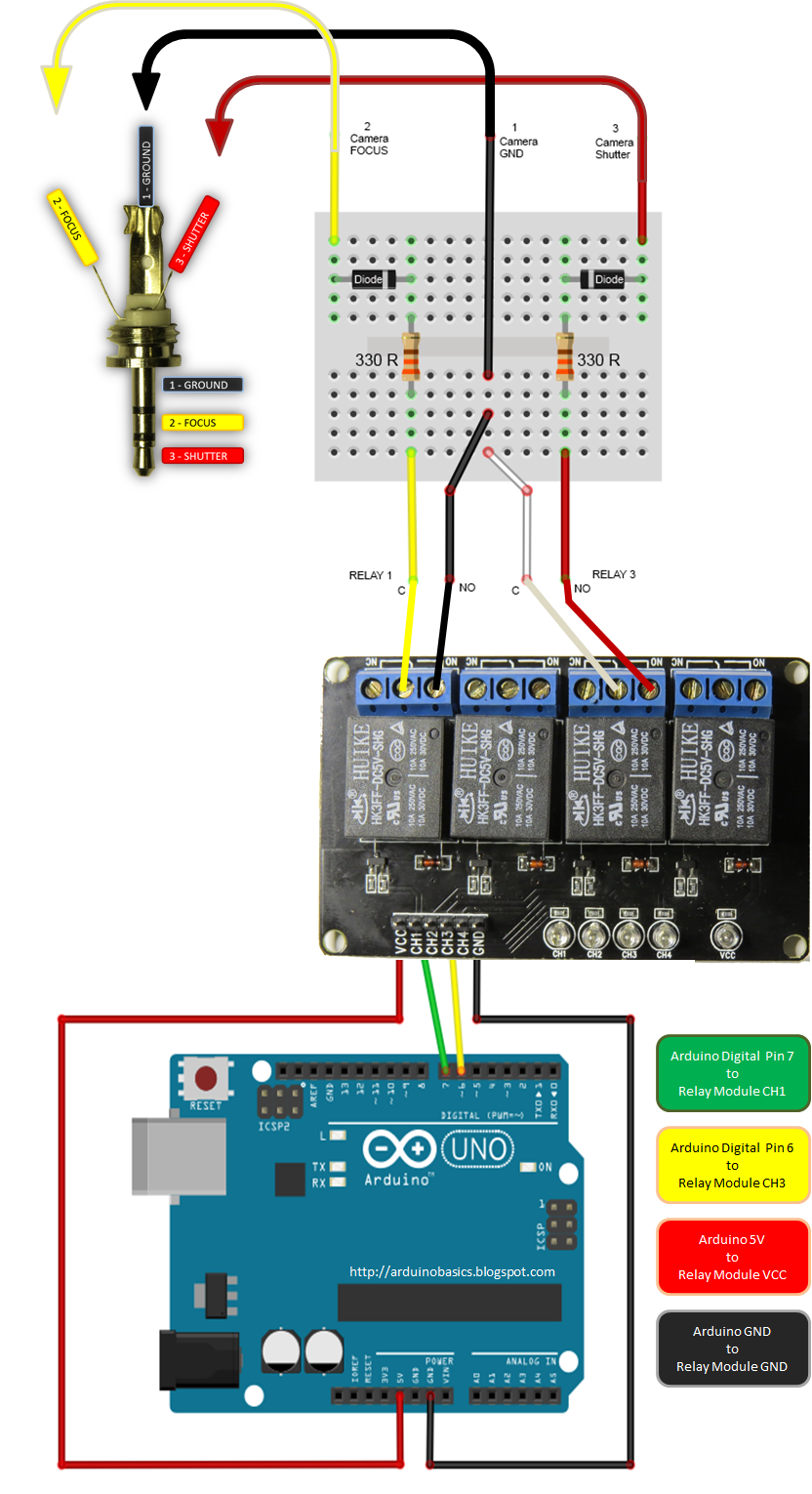
I found out that my Canon Powershot SX50 HS camera has a port on the side for a remote switch. In the "Optional Accessories" section of the camera brochure, it identifies the remote switch model as RS-60E3. I then looked up the model number on this website to find out the size of the jack (3 core, 2.5mm), and the pinout (Ground, focus and shutter) required to emulate the remote switch. Once I had this information, I was able to solder some really long wires to the jack and connect up the circuit (as described below).
 
I use Time-Lapse tool to stitch all of the pictures together to create a movie/animation.
 
You will need to download and install the LED_Bar library from Seeedstudio into your Arduino IDE libraries folder in order to use the LED Bar in this tutorial. For more information about the LED Bar - visit the LED Bar Seeed-Studio wiki.
 

Parts Required:


Fritzing Sketch


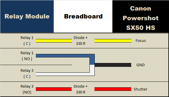
Connection Tables


Arduino to Relay Module:


Relay Module to Camera:


Arduino to Slide Potentiometer:


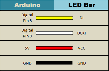
Arduino to LED Bar:


Arduino Sketch


  1
2
3
4
5
6
7
8
9
10
11
12
13
14
15
16
17
18
19
20
21
22
23
24
25
26
27
28
29
30
31
32
33
34
35
36
37
38
39
40
41
42
43
44
45
46
47
48
49
50
51
52
53
54
55
56
57
58
59
60
61
62
63
64
65
66

/* ===============================================================
      Project: DIY Canon Intervalometer using Arduino
       Author: Scott C
      Created: 9th October 2014
  Arduino IDE: 1.0.5
      Website: http://arduinobasics.blogspot.com/p/arduino-basics-projects-page.html
  Description: Use Arduino as an intervalometer for Canon PowerShot SX50 HS
               A slide potentiometer is used to control the time between photos.
               The LED Bar is used to display the delay between photos.
               A 3 core 2.5mm jack is used to connect the Arduino and Relay module to the Camera.
================================================================== */

 /* You will need to download and install the LED_Bar library from here: https://github.com/Seeed-Studio/Grove_LED_Bar */
 #include <LED_Bar.h>

 /* Connect 5V on Arduino to VCC on Relay Module
    Connect GND on Arduino to GND on Relay Module */

 #define CH1 7   // Connect Digital Pin 7 on Arduino to CH1 on Relay Module
 #define CH3 6   // Connect Digital Pin 6 on Arduino to CH3 on Relay Module
 
 int potPin=A0; //Connect Slide potentiometer to Analog Pin 0 on Grove Base Shield
 int potValue=0; //The variable used to hold the value of the potentiometer

 LED_Bar bar1(9,8); //Connect LED Bar to Digital I/O 8 on Grove base shield.
                   //The LED Bar actually uses digital pin 8 and 9.

 voidsetup(){
   pinMode(CH1, OUTPUT);
   pinMode(CH3, OUTPUT);
   
   //Turn OFF any power to the Relay channels
   digitalWrite(CH1,LOW);
   digitalWrite(CH3,LOW);
   delay(2000); //Wait 2 seconds before starting sequence
   
   //Focus camera by switching Relay 1
   digitalWrite(CH1, HIGH);
   delay(2000);
   digitalWrite(CH1, LOW); //Stop focus
   delay(3000);
 }

 voidloop(){
      // Read the slide potentiometer and convert the reading to a value between 0 and 10.
      potValue=constrain(map(analogRead(potPin),0,1000,0,10),0,10);
      
      //Use the pot value to create a visual count-down display on the LED bar.
      for(int i = potValue; i>0; i--){
        bar1.setLevel(i);
        delay(1000);
      }
      
      //If the pot value is less than 1, then delay for 30 seconds.
      if(potValue<1){
        delay(30000);
      }
      
      //Turn LED Bar off when taking photo
      bar1.setLevelReverse(0);
      
      //Press shutter button for 0.1 seconds. Modify delay if required.
      digitalWrite(CH3, HIGH);
      delay(100);
      digitalWrite(CH3,LOW); //Release shutter button
 }


The Video


This project shows how to make your Canon Powershot SX50 HS a whole lot smarter using an Arduino. There are so many things that look so different with an intervalometer. While I connected a slide potentiometer to the Arduino to provide extra flexibility, and an LED Bar for visual feedback, there are many other sensors out there that can be combined with the camera. For example, you could use a PIR sensor to take a picture when movement is detected. Or take a picture when a laser trip-wire is broken. What about sound activation, light activation, leak detection.... the options are limitless.
 
This has been one of my favorite projects, it was a lot of fun, and very interesting.
I highly recommend that you try it out!


If you like this page, please do me a favour and show your appreciation :


Visit my ArduinoBasics Google + page.
Follow me on Twitter by looking for ScottC @ArduinoBasics.
Have a look at my videos on my YouTube channel.


However, if you do not have a google profile...
Feel free to share this page with your friends in any way you see fit.

Hacking Robotic Arm using Controllino and Cayenne

$
0
0


Description

This tutorial will show you how to take over the controls of the OWI Robotic Arm with the help of an Arduino compatible, open-source PLC called the Controllino MAXI, together with Cayenne (my go-to iOT application for remote connection to my Arduino projects). The Controllino MAXI will provide the physical connections to the OWI robotic arm, and Cayenne will allow me to control the arm via my web browser or via the Cayenne app on my phone.


Arduino Libraries and IDE

  1. The Arduino IDE can be used to program the Controllino. You can dowload the Arduino IDE from here: https://www.arduino.cc/en/main/software.
  2. You will also need to read the Cayenne Ethernet library installation instructions in order to install the Cayenne Ethernet Library.
  3. The Controllino will connect to the internet via the Ethernet port onboard.
  4. You do not need the Controllino library for this project, however, if you have a Controllino, you might as well install the library. You can read the Controllino library installation instructions from their GitHub webpage here: https://github.com/CONTROLLINO-PLC/CONTROLLINO_Library.
  5. You will need to notify the Arduino IDE of the Controllino MAXI board by pasting the supplied URL into the "Additional Boards Manager URLs" in the Arduino IDE.
  6. This is located under: FILE - PREFERENCES - Additional Boards Manager URLs.
  7. The URL that you need to paste is in STEP 3 of the Controllino Library installation instructions on their GitHub page.
  8. The video at the top of this tutorial may help clarify the process.


ARDUINO CODE:

The code above is very simple, however you will need to create a dashboard of widgets from within your Cayenne account in order to control the OWI robotic Arm from your phone or via the Dashboard webpage.


Setting up Cayenne Dashboard

Once you have created your Cayenne account, you will be presented with a webpage to choose a board to connect to. Controllino is an Arduino compatible PLC, so make sure to follow these instructions for setting up the Controllino in your Cayenne Account.

  1. Select Arduino from the available list of boards.
  2. Make sure to install the necessary libraries if your have not done so already.
  3. Select Arduino MEGA from the avaliable list of Arduino boards
  4. Select Ethernet Shield W5100
  5. Copy and paste the Arduino code that pops up on screen into your Arduino IDE and upload to the Controllino.
  6. Alternatively, copy and paste the code from above, however you will need to insert your Authentication token to get it to work

After you upload the code to the Controllino, and providing it has an ethernet cable connected to the internet router (and has access to the internet), and is powered on, it will connect to your Cayenne Dashboard. You can now add widgets to the dashboard in real time to interact with the Controllino, and without uploading any more code to the open source PLC.


Adding Widgets

We need to add a number of widgets in order to activate the relays on the Controllino. The relavent digital pins that we will need to know about can be found on the Controllino website here: https://controllino.biz/downloads/.

Here is the direct link to the PINOUT file for the Controllino MAXI.

"Armed" with that knowledge, we can now create the widgets which are necessary to control the relays on the Controllino. From within the Cayenne dashboard, please follow these instructions to create a widget:

  1. Select - ADD NEW
  2. Select - DEVICE/WIDGET
  3. Select - ACTUATORS
  4. Then - RELAY from the dropdown box
  5. Select - RELAY SWITCH
  6. Give the widget a descriptive name to differentiate it from the other widgets and a name that is somewhat informative (eg. R0 - Pos)
  7. I gave the first widget the name "R0 - Pos", because it will connect to Relay R0, and that relay will be connected to the Positive (POS) terminal of the OWI robotic arm.
  8. Select the device you would like to connect to. Be aware that you can change the name of the device in the settings. If you followed this tutorial, it should have the name "Arduino MEGA", but I changed the name of the device to "Controllino" to be more accurate.
  9. We will be using a digital pin to control the relay, therefore select "Digital" as the Connectivity option
  10. For this specific widget, we will be controlling R0, which is activated by digital pin D22 on the Controllino. Therefore select "D22" from the "Pin" dropdown box.
  11. Choose a "Button" as the widget type
  12. Choose an icon from the dropdown box that makes sense to you
  13. Skip Step 1
  14. Select Step 2: Add actuator

You should now see your new widget on the dashboard. Select the widget to enable or activate that relay. If you do this, and if everything goes to plan, you will see the LED for R0 illuminate on the Controllino. You now have to add the rest of the widgets to the dashboard in order to control the rest of the relays on the Controllino.


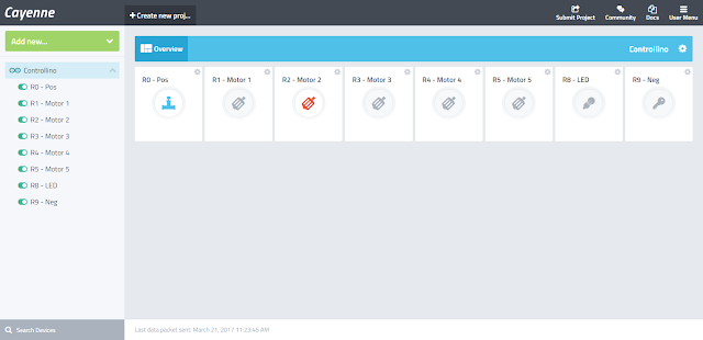
Widget Dashboard

Here is a table to show you how I setup my dashboard.


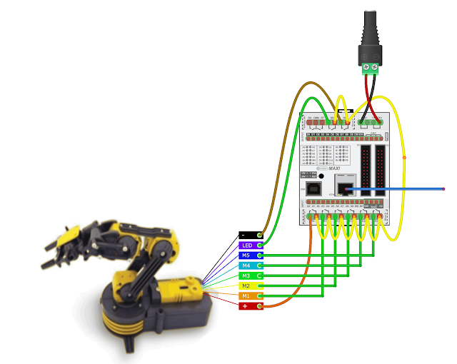
Fritzing diagram


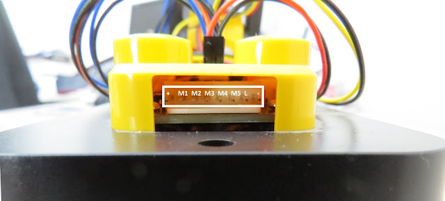
OWI Robotic Arm Pins


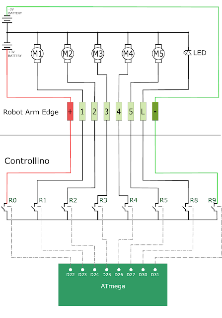
Normal OWI Robotic Arm Circuit

The following circuit diagram will show you how the wired control box is normally connected to the OWI Robotic arm. This is the circuit diagram of the OWI robotic arm under normal operating contidtions.


OWI Robotic Arm Circuit when connected to Controllino

The following circuit diagram will show you how the OWI Robotic Arm will be controlled by the relays of the Controllino. This is the circuit diagram of the OWI robotic arm when it is connected to the Controllino.


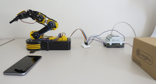
All connected

The OWI Robotic Arm is connected to a breadboard using the female-to-male jumper wires. Solid core wire is then fed through to the relay terminals of the Controllino. You could just wire it up so that the robotic arm is connected directly to the Controllino, however, I did not have the right connectors for this purpose.
The Controllino is also connected to my internet router via a normal RJ-45 ethernet cable, and is powered by a 12V DC power adapter.


Summary

Now that you have all the physical connections made, uploaded the code to the Controllino, and have created your dashboard in Cayenne, you should be able to control your OWI Robotic arm from anywhere in the world. As demonstrated in the video at the start of this tutorial, the robotic arm has quite a bit of give on each of the joints, which makes it difficult to achieve certain tasks that require an element of precision. There goes that idea of being able to perform surgery with this thing !!! At least you can get it to make you a cup of tea, and if you are patient enough, you might even get a grape once in a while.

Thank you to Controllino and Cayenne for making this tutorial possible. If you would like your product featured in my tutorials, please contact me on my contact page.


If you like this page, please do me a favour and show your appreciation :

 
Visit my ArduinoBasics Google + page.
Follow me on Twitter by looking for ScottC @ArduinoBasics.
I can also be found on Pinterest and Instagram.
Have a look at my videos on my YouTube channel.

Nextion Enhanced Stepper Motor Piano Project

$
0
0

Introduction

Nextion is a programmable human machine interface (HMI) that can be customized and designed to simplify the interaction between you and your project.

This Nextion Enhanced module (NX4827K043) with a resistive touch screen display, has some additional features not seen in previous traditional versions of the Nextion series.

  • A built in real time clock (RTC)
  • Accessible flash memory (32MB)
  • GPIO functionality
  • Faster clock speed

Before you connect the Nextion Enhanced module to your project, you need to design your interface with the free Nextion Editor. The editor can be downloaded here.

In this project, I will be designing a simple dynamic interface, which will allow me to interact with a stepper motor in two different ways.

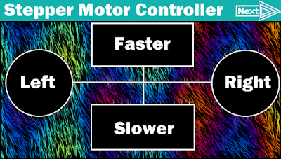
The first interface will let me control the direction and speed of the stepper motor through the use of a simple GUI. I will have left and right arrows for the direction, and up and down arrows for the speed. I will also map the Expansion board to this interface for a more tactile experience.

The second interface will be more musical in nature. I will design a functional “Stepper motor piano” that will allow me to play simple songs using the rotational sounds of the stepper motor. This concept is not new, but I will show you how easy it is to make.


Project Scope

My project will show a splash screen when the project is powered up. After 3 seconds, the first interface will display.

The first interface will have 4 arrows:

  1. Left and Right arrows for the stepper motor direction of rotation
  2. Up and down arrows to increase/decrease stepper motor rotational speed
  3. Next Page button – to jump to the next interface

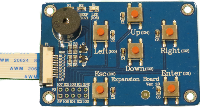
Each arrow/button on the first interface will be mapped to a specific button on the expansion board. Eg.

  1. Left/Right arrow is mapped to Left/Right button
  2. Up/Down arrow is mapped to Up/Down button
  3. Next page button is mapped to Enter button on the expansion board

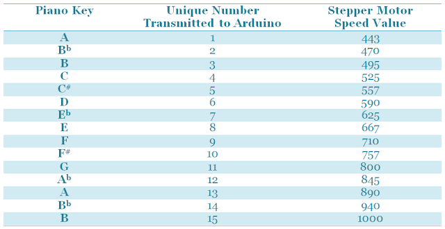
The second interface will look like a piano on the Nextion Enhanced display. Each key on the piano will transmit a specific and unique number to the Arduino.

The specific number received by the Arduino will allow it to set the speed of stepper motor which will ultimately affect the frequency of sound it produces. Therefore when the “C” key is pressed on the Nextion display, the stepper motor will rotate at a frequency that sounds like a “C” note.


The stepper motor speeds can be determined by tuning the motor to specific notes using the first interface and an iPhone app called Tuner T1 Free".

If you plan to replicate this project, you will need to determine the relevant speeds of your own stepper motor, and substitute your values into the Arduino code later on in this tutorial.


Create a New Project

The first step is to create the interfaces in the Nextion Editor on your PC. You can download the Nextion Editor here.. Load up the Nextion Editor and create a new project.

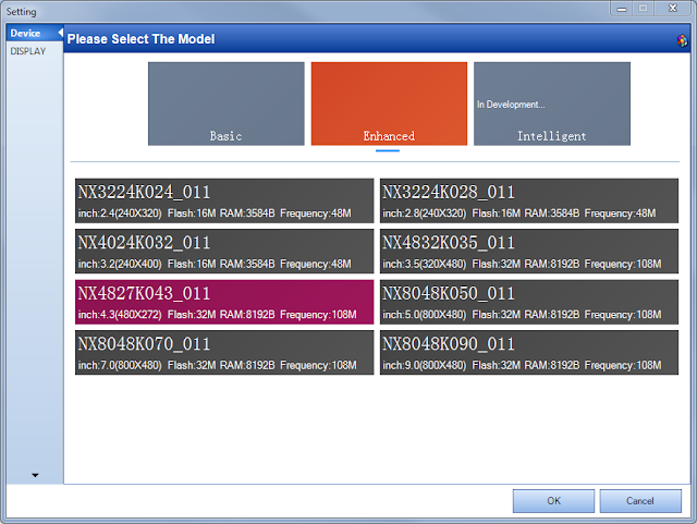
When you start a new project, you need to make sure that you select the correct Nextion device from the available options.

I am using the “Nextion Enhanced NX4827K043” device.

  1. Select File → New
  2. Select a name for the project and save it to a suitable place on the hard drive
  3. Select the appropriate Nextion device from the available options
    1. My device has a screen size of 480 x 272 pixels


Project Resources

You need to import all of the resources (eg. pictures and fonts) into your project, and then design the interface to suit your specific needs.

Fonts

I will not be using any fonts in my project, but if you wanted to write any text to the display, you will need to generate a font in the Nextion Editor.

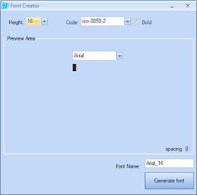
  1. Tools → Font Generator
    1. Select the Height of the Font (eg. 16)
    2. Select the Font code type (eg. iso-8859-2)
    3. Select if you want it to be in Bold or not
    4. Choose the Font you want to use (eg. Arial)
    5. Choose the spacing (eg. 0)
    6. And finally give this Font a unique name (e.g. Arial_16)
    7. Push the “Generate Font” button on the bottom right of the window

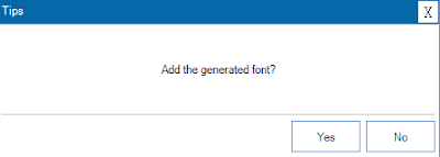
Once you press the Generate Font button, it will get you to save the font using a *.zi extension, and will automatically ask you if you would like to “Add the generated font?” to the project. If you are happy with the font, and would like to use this font in your project, then select “Yes”, otherwise select “No” and start again.

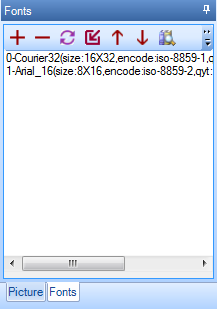
You cannot add any text to your project until you have imported or added a font. All of your project fonts will be displayed in the fonts window.

Each font will automatically be indexed, so that you can reference the font programmatically if required. In fact all resources that you add to your project are assigned a number and incremented by one for every resource added. For some resources, you can see this number to the left of the item. E.g. In the picture above, the Courier Font has an index of 0, whereas the Arial font has an index of 1. If you delete a resource, the index number may change for that item.


Pictures

As I said before, I will not be using any fonts for my project because the words on the screen will not be changing in any way. I can get away with designing a “Picture” and importing that into the project. I will need 3 pictures for my project.

  1. Splash screen
  2. Stepper Motor Controller
  3. Stepper Motor Piano

On the Nextion Enhanced NX4827K043 device, each picture must be

  • 480 x 272 pixels in size

We will now import the following pictures into the Nextion Editor so that we can use them in the project.

In the bottom left hand corner of the Nextion editor is the “Fonts and Picture” resource window:

  1. Select the Picture tab
  2. Then select the “+” icon
  3. This will open a dialog box to allow you to select the picture(s) to add to the project. You can select more than one picture to import.

I imported the following pictures from my computer:


Splash Screen


Interface 1: Stepper Motor Controller


Interface 2: Stepper Motor Piano


Creating the GUI

Pages

Every resource will get an ID based on the order it is added, and each resource will automatically get a name. You can change the name of the resource or object, but you cannot edit the ID.

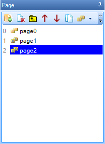
Three pages will be designed to meet the criteria described above.

To add a page, you simply select the “Add” icon from the “page window”. And keep adding pages until you have a total of 3 pages (page0, page1 and page2).


Page 0 - Splash Screen

When the Nextion is powered up, the splash screen will be displayed for 3 seconds before it shows the Stepper Motor Controller screen. I used the following steps to create the splash screen.

  1. Add the splash screen picture to page0
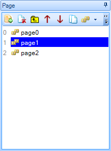
    1. Select “page0” from the Page window
    2. Select “Picture” from the Toolbox window
    3. Double-click the “pic” attribute from the Attribute window
    4. Select the splash screen image from the list
    5. Press the OK button
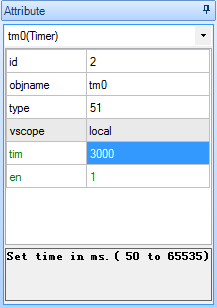
  2. Add a Timer to page0
    1. Select Timer from the Toolbox window
    2. Change the “tim” attribute from 400 to 3000 in the Attribute window
    3. Enter “page page1” in the User code section of the Timer Event(0)

This timer event will make the Nextion jump to page1 after 3 seconds.


Page 1 - Stepper Motor Controller

This page is designed to control the direction and speed of the stepper motor.

There will be two buttons for the direction (Left and Right), and two buttons for the speed (Faster and Slower). And one more button to jump to the next page (i.e. the Stepper Motor Piano page). These buttons will also be mapped to the Nextion expansion board. The tactile buttons of the expansion board will provide an alternative method of controlling the motor.

  1. Add the Stepper Motor Controller picture to page1
    1. Select “page1” from the Page window
    2. Select “Picture” from the Toolbox window
    3. Double-click the “pic” attribute from the Attribute window
    4. Select the “Stepper Motor Controller” image from the list
    5. Press the OK button
  2. Add Hotspots over each button on the Stepper Motor Controller image
    1. Select “Hotspot” from the Toolbox window
    2. Drag and resize the Hotspot so that it covers the “Left” button
      1. This is the area that will respond to “Left button” presses.
      2. It will be transparent when uploaded to the Nextion board
    3. Select the “Touch Press Event” tab in the Event window
    4. Un-Check the “Send Component ID” checkbox
    5. Type the following code into the “User Code” Section of the Event window:
      • print “L”
    6. Change the object name of the hotspot to “Left” using the following process:
      1. Select objname from the attribute window and change the text from “m0” to “Left”
      2. It is not compulsory to change the hotspot object name; however it will help later on.
    7. Repeat steps 2a-2f for each of the other buttons in the following order and as per the table below
      1. Right
      2. Faster
      3. Slower
      4. Next

The decimal ASCII code for the letter “L” is 76, hence when the Nextion Enhanced display sends the letter L to the Arduino using the print “L” command, the Arduino will receive the number 76. When the right button is pressed, it will receive the number 82, and so on.

The “Next” button does not transmit anything to the Arduino, it is simply there to jump to the next interface on the Nextion Enhanced display, hence the reason why the user code is different for that button.

  1. Map the buttons to the Expansion board
    1. Select “page0” and then “page1” from the Page window
    2. Select the “Preinitialize Event” tab from the Event window
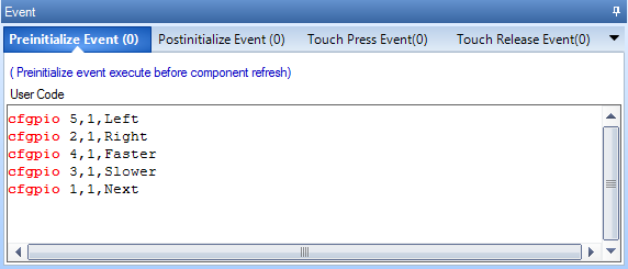
    3. Enter the following code into the “User Code” field of the Preinitialize Event tab:
      • cfgpio 5,1,Left
      • cfgpio 2,1,Right
      • cfgpio 4,1,Faster
      • cfgpio 3,1,Slower
      • cfgpio 1,1,Next

Please note: There is one space between cfgpio and the number next to it, but there are no other spaces on each line. If you introduce extra spaces, it will not compile.

This code maps the buttons on the expansion board to the hotspot objects on page1. For example, when the Left button (IO5) on the expansion board is pressed, it simulates the actions or events associated with hotspot m0/Left. In this case it will send a value of “L” (76) to the Arduino.

The IO number is marked within brackets on the expansion board.


Page 2 - Stepper Motor Piano

This interface will be designed to look like a piano, and will allow me to control the stepper motor such that it produces a note in the same key as the one I press on the Nextion display. The stepper motor will produce the note by rotating at a specific frequency.

  1. Add the Stepper Motor Piano picture to page2
    1. Select “page2” from the Page window
    2. Select “Picture” from the Toolbox window
    3. Double-click the “pic” attribute from the Attribute window
    4. Select the “Stepper Motor Piano” image from the list
    5. Press the OK button
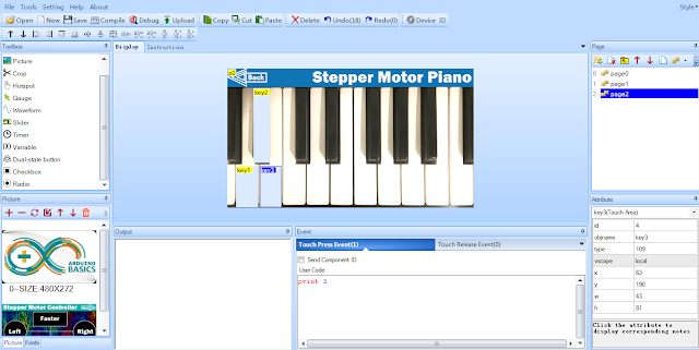
  2. Add Hotspots over each key on the Stepper Motor Piano image
    1. Select “Hotspot” from the Toolbox window
    2. Drag and resize the Hotspot so that it covers the the “A” key.
      1. This is the area that will respond to “A-key” presses.
      2. It will be transparent when uploaded to the Nextion board
    3. Select the “Touch Press Event” tab in the Event window
    4. Type the following into the “User Code” section
      • print 1
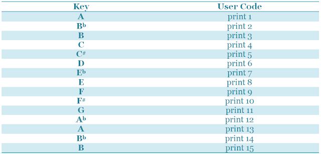
    5. Repeat steps 2a-2d for each of the other keys as per the table below

When the specific key is pressed, the Nextion Enhanced board will transmit the printed number, followed by three 0x00 values. The terminating values can be ignored.

  1. The “Back” button will allow me to jump back to the previous interface on the Nextion Enhanced board.
    1. Create a hotspot for the back button using the following process:
      1. Select Hotspot from the Toolbox window
      2. Move/Resize the hotspot over the “Back” button
    2. Select the Event window
    3. Make sure the “Touch press event” tab is selected
    4. Type:   page page1   into the User Code section


Debugging

The good thing about the Nextion Editor, is that you can test out the interface functionality before uploading it to the board.

  1. Save the project by pressing the save button on the task bar
  2. Then press the compile button
  3. Then press the debug button.

A Nextion emulator window will appear. This window should respond in the same manner as Nextion module after the Nextion file is uploaded to the board. This emulator is a great way to test out your interface and to make sure it looks and works as expected. Once I was happy with the interface(s), I transferred the compiled Nextion file onto an SD card:

  1. Press the compile button
  2. File → Open Build Folder
  3. Select the *.tft file with the same name as that of the project
  4. Copy it to a micro SDHC card
  5. Insert the SDHC card into the SD card slot on the Nextion display
  6. Power up the Nextion board

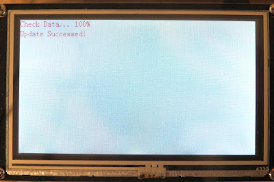
Wait for the file to flash the Nextion board, and you should see a message that looks like this:

The next step is to power off the Nextion board, and remove the SDHC card.


ARDUINO SETUP

The Nextion Enhanced display is ready, and now it is the Arduino’s turn. The Arduino is programmed to receive Serial messages from the Nextion Enhanced display and control the stepper motor based on the letters or numbers received. The unique letters or numbers being transmitted from the Nextion board, allow the Arduino to understand what button is being pressed, and it uses those numbers or letters to control the flow of code in order to perform specific stepper motor actions.


Arduino Libraries and IDE

The Arduino IDE can be downloaded from this site.

The SoftwareSerial library is used to enable Serial communication between the Arduino and the Nextion Enhanced display.

The AccelStepper library is used to simplify the process of stepper motor control.


ARDUINO CODE:

Here is the Arduino Code for this project:

I set up a maximum and minimum speed for the motors, and some pre-defined keys. It is possible to “tune” the motor using the first interface of the Nextion display. You can do this by making the motor turn faster or slower until you reach the desired key.

I used the “Tuner T1 Free” app from the iTunes app store to identify WHEN the motor was producing a note in key.

When the motor was producing a specific note, I would write down the stepper motor speed that was printed to the Serial monitor window. Every time the motor speed is increased or decreased, the Arduino code prints the speed to the serial monitor window. I then use these speeds to update the notes[] array in the Arduino code.

The notes[] array holds the stepper motor speeds that correspond to the individual notes on the piano. The Nextion display essentially sends the index number of the note to play from the notes array on the Arduino, thereby simplifying the code required to spin the motor at 16 different speeds.


Hooking it up:

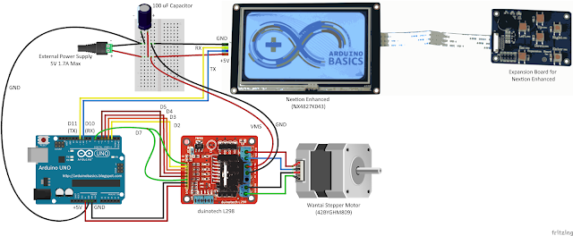
With all boards powered off, the next step is to make all of the necessary hardware connections to the Arduino. There are two major sections to consider,

  1. The Stepper motor driver and motor
  2. The Nextion Enhanced board

You need to ensure that you use an external power source to power both the stepper motor and the Nextion Enhanced board. The stepper motor driver board itself was powered by the Arduino without any problems, but the actual stepper motor will need an external power supply. The Nextion Enhanced board also needs an external power supply because it requires more current than the Arduino can safely provide.

Here is how you would connect the Arduino to the Stepper motor driver board and associated stepper motor.


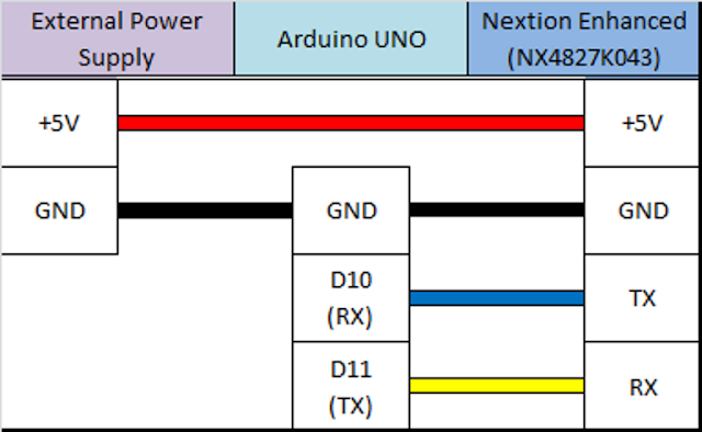
And this is how you would connect the Arduino to the Nextion Enhanced display


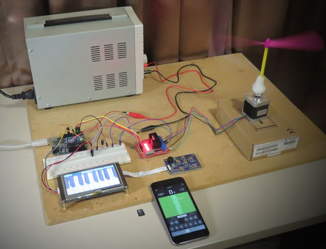
And this is what it looked like when I put it all together:


Make note of the external power supply used. I made sure that I had a large enough power supply to handle the power requirements of the project, and utilized the relevant datasheets to help me identify those requirements. If you plan to replicate this project, make sure you take into consideration the specific power requirements of your motor, your motor driver and your Nextion display. The Arduino can only supply 400mA of current from the 5V pin.

With everything hooked up, I powered up the Nextion display, then powered up the Arduino. The stepper motor starts spinning automatically. I used the first interface to change the direction and/or speed of the motor. Please note the maximum and minimum speeds set up in the Arduino code.

I then used the Next button to jump to the second interface on the Nextion Enhanced display. The second interface looks like a piano. And when I press a key on the piano display, the motor changes speed to match the note I pressed.

Voila !! The stepper motor piano is born !!

I played a number of simple tunes on the Stepper motor piano and was surprised how well it worked. Very clever !!


Concluding comments

This project is relatively simple, but stepper motors can be tricky to set up and tune. Nothing a bit of determination cannot fix.

This project was a lot of fun. If you plan to replicate this project, I would be interested to see your versions, or just knowing if this helped you in any way.


This project would not have been possible without the collaborative efforts of iTead Studio. Their Nextion Enhanced display has a lot more to offer than what I have shown you here. But hopefully this tutorial gives you some insight into the power of such a display, and perhaps how it could improve the project you are currently working on. The only thing I did not like was the power requirements. I would have preferred something within Arduino power supply limits. Nevertheless, I am very happy with the Nextion Enhanced display, and would recommend it to anyone looking for a Human Machine interface to include in their project. You can see how simple it was to create TWO interfaces for my project, and I only scratched the surface.

The original ArduinoBasics Blog

E-Paper Barcode 39

$
0
0

E-Paper (or Electronic paper) is a display technology that mimics the appearance of ordinary ink on paper. E-paper displays do not emit light, rather they reflect light, thus making them much more comfortable to read and provide a wider viewing angle than most light emitting displays (source: Wikipedia).

I printed something to an E-paper display, unplugged it, and could still read the message clearly months later. These E-paper displays are great for showing information that is static for long periods. You only need to provide power when the data or information needs updating.

Barcodes are used everywhere, and one of the simplest Barcodes to generate is the Code 39 format (also known as Code 3 of 9). I used an E-paper shield and E-paper module to display a number in this barcode format. I then tested it with a Barcode reader and it worked perfectly.
This tutorial will show you how to send a number to the Arduino from the Serial Monitor, and display the Barcode on the E-paper module.

Note: If you are using an Arduino UNO (or compatible), you will also need to get a micro SDHC card.
 

The Video


The video will show you how to assemble the shield and the module onto the Arduino, and also how to install the SDHC card.


Parts Required:

Library Download


To use the e-paper shield, you will need to download the Small e-paper Shield library.
This library will allow you to use the following functions on the e-paper shield:
  • begin : to set up the size of the e-paper panel
  • setDirection : to set up the display direction
  • drawChar : to display a Character at a specified position
  • drawString : to display a String of characters at a specified position
  • drawNumber and drawFloat : to display a number
  • drawLine : to draw a line
  • drawHorizontalLine : to draw a horizontal line
  • drawVerticalLine : to draw a vertical line
  • drawCircle : to draw a circle
  • fillCircle : to draw and fill a circle
  • drawRectangle : to draw a rectangle
  • fillRectangle : to draw and fill a rectangle
  • drawTriangle : to draw a triangle
You can also draw an image to the e-paper shield.

For more information on how to use these functions, please visit the seeedstudio wiki. If you are unfamiliar with installing libraries - then have a look at the following sites:

Barcode 39 Info

Barcode 39 (or Code 3 of 9) is a barcode that consists of black and white vertical lines. These lines can be thick or thin. Each character can be coded using 9 alternating black and white bars. The barcode always starts with a black bar, and ends with a black bar.

If you code using thin lines only, then each character can be coded using a total of 12 bars. A wide black line is essentially two thin black lines next to each other. Same goes for a wide white line. Because there are now only 2 options (black or white), you can create a binary code. I used a 1 for black bars, and 0 for white bars. If there was a thick black bar, then this would be represented with a 11. A thick white bar would be 00.

Each barcode sequence starts and ends with a hidden * character. Therefore if you were to display just the number 1, you would have to provide the code for *1*.

  • * = 100101101101
  • 1 = 110100101011
  • * = 100101101101
Notice that each character starts with a 1 and ends with a 1.
Something also to take note of: is that each character is separated by a thin white line (and not represented in the binary code).

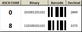
All of these 0's and 1's can get a bit confusing, so I decided to represent these binary numbers as decimals. For example, the picture below shows how a 0 and an 8 would be coded (without the *):


The table below provides the binary and decimal codes for each number used in this tutorial. I have also included for your own reference, each letter of the alphabet, however I did not use these in this tutorial.

The binary representation of each character in this table was obtained from this site.
www.barcodeisland.com is a great resource of information about barcodes.

I adapted their binary code into a decimal equivalent, and therefore had to create my own table.


Arduino Sketch


  1
2
3
4
5
6
7
8
9
10
11
12
13
14
15
16
17
18
19
20
21
22
23
24
25
26
27
28
29
30
31
32
33
34
35
36
37
38
39
40
41
42
43
44
45
46
47
48
49
50
51
52
53
54
55
56
57
58
59
60
61
62
63
64
65
66
67
68
69
70
71
72
73
74
75
76
77
78
79
80
81
82
83
84
85
86
87
88
89
90
91
92
93
94
95
96
97
98
99
100
101
102
103
104
105
106
107
108
109
110
111
112
113


/* ===============================================================
      Project: Display Barcodes on an e-Paper Panel
       Author: Scott C
      Created: 6th January 2015
  Arduino IDE: 1.0.5
      Website: http://arduinobasics.blogspot.com/p/arduino-basics-projects-page.html
  Description: This project will allow you to send a number from the Serial 
               Monitor to the Arduino. The number will then be displayed on 
               the e-Paper panel as a Code-39 barcode (and text).
================================================================== */

#include <ePaper.h>
#include <SPI.h>
#include <SD.h>
#include "GT20L16_drive.h"

constint maxBarcodeSize = 10; // set the maximum barcode size to 10 digits
int barcode[maxBarcodeSize]; // initialise the barcode array to the maximum 10 digits
int barcodeText[maxBarcodeSize]; // initialise the barcodeText array to the maximum 10 digits
int barcodePos; // Used to identify each digit within the barcode
int barcodeLength; // Used to identify the actual length of the barcode

/*  The following array holds the decimal code for each digit (0-9). 
    Each digit can be converted to binary and then drawn as a barcode.
                         0     1     2     3     4     5     6     7     8     9         */
int barcodeDecimal[] = {2669, 3371, 2859, 3477, 2667, 3381, 2869, 2651, 3373, 2861};

int astrix = 2413; // "*" character decimal code used at beginning and end of barcode sequence


/*  When drawBarcode = "no", the program will not draw the barcode on the e-paper panel
    When drawBarcode = "yes", the command to draw the barcode on the e-paper panel will be triggered. */
String drawBarcode = "no";


/*  This variable is the x Position on the e-Paper panel screen */
int xPosition;


voidsetup(){
    Serial.begin(9600); // Initialise Serial communication
    EPAPER.begin(EPD_2_0); // Set the e-Paper panel size to 2 inches
    EPAPER.setDirection(DIRNORMAL); // Set the e-Paper panel display direction (to Normal)
    eSD.begin(EPD_2_0); // Prepares the SD card
    GT20L16.begin(); // Initialise the GT20L16 font chip on the e-Paper panel
    barcodePos = 0;                    // Set the barcode digit to the first digit in the barcode
    EPAPER.clear_sd(); // Clear the screen when starting sketch
    
    EPAPER.drawString("http://arduinobasics", 10, 20); //splash screen text
    EPAPER.drawString(".blogspot.com", 60, 40);
    
    EPAPER.display(); // Display the splash screen
}


voidloop(){
  
    // The Arduino will wait until it receives data from the Serial COM port
    
    while (Serial.available()>0){
      barcodeText[barcodePos] = Serial.read();
        
      if(barcodeText[barcodePos]>47 && barcodeText[barcodePos]<58){ // A number was sent
         barcode[barcodePos] = barcodeText[barcodePos]-48;            // Convert the decimal value from the serial monitor to a Number
      } 
      
      if(barcodeText[barcodePos]==46){ // If a "." is detected, then barcode is complete
        barcodeLength = barcodePos;                   // Set the length of the barcode (used later)
        drawBarcode = "yes"; // We can now draw the barcode
        
      }
      
      if(barcodePos>(maxBarcodeSize-1)){ // Check if maximum barcode length has been reached
       barcodeLength = barcodePos;                    // Set the length of the barcode (used later)
       drawBarcode = "yes"; // We can now draw the barcode
      }
     
       barcodePos++;                                  // Move to the next barcode digit
    }
    
    if(drawBarcode == "yes"){ // Only draw the barcode when drawBarcode = "yes"
      
      EPAPER.clear_sd(); // Clear the e-Paper panel in preparation for barcode
      xPosition = 15;                                 // Set the initial white-space on the left
      drawBCode(astrix, ''); // Each barcode starts with an invisible *
      
      for(int digit=0; digit<barcodeLength; digit++){ // Start drawing the barcode numbers
        drawBCode(barcodeDecimal[barcode[digit]], barcodeText[digit]);  // Call the drawBCode method (see below)
      }
      
      drawBCode(astrix, ''); // Each barcode ends with an invisible *
      EPAPER.display(); // Show the barcode image and text
      
      drawBarcode = "no"; // Stop it from drawing again until next barcode sequence sent
      barcodePos=0;                                   // Re-initialise the position back to first digit (in preparation for the next barcode)
    }
}


//The drawBCode method is the key method for drawing the barcode on the e-paper panel
void drawBCode(int bCode, char bCodeText){
  xPosition++;                                        // There is a white space between each digit
  for (int barPos = 11; barPos > -1; barPos--){ // Cycle through the binary code for each digit. Each digit is made up of 11 bars
    xPosition++;                                      // Advance the xPosition to draw the next bar (white or black)
    if(bitRead(bCode, barPos)==1){ // If the binary digit at this position is a 1, then draw a black line
      EPAPER.drawVerticalLine(xPosition, 10, 60); // This draws the individual Bar (black - only)
    }                                                 // If the binary digit is a 0, then it is left blank (or white).
  }
  EPAPER.drawChar(bCodeText, xPosition-9, 75); // Draw the human readable (text) portion of the barcode
}


There is something weird about the E-paper shield library which tends to display the word "temperature:" in the Serial monitor when opened, and with each serial transmission. Don't worry about this. Just ignore it.'


This tutorial shows you how to create your own renewable barcodes. While this only handles numbers at this stage, it could just as easily be upgraded to handle text as well. If you liked this tutorial, please give it a google+ thumbs up, share it with your friends, or just write a comment. Thankyou for visiting my blog.


If you like this page, please do me a favour and show your appreciation :

 
Visit my ArduinoBasics Google + page.
Follow me on Twitter by looking for ScottC @ArduinoBasics.
Have a look at my videos on my YouTube channel.


However, if you do not have a google profile...
Feel free to share this page with your friends in any way you see fit.

A list of Arduino Tutorial sites

$
0
0
I have just created a new page on my blog which lists a huge number of websites and YouTube channels that are dedicated to creating Arduino tutorials. If you are learning to use the Arduino, this page will definitely point you in the right direction.

Please let me know if I have missed any obvious sites.

Link :  Arduino Tutorial Site List

A List of Arduino IDE alternatives

$
0
0

Looking for an Arduino IDE alternative?
Please see my list of 25+ IDEs that you can use to program your Arduino.
From command line to visual drag-and-drop interfaces, you are sure to find an IDE that suits your programming style.

I will keep updating that page as I find new alternatives, so please make sure to bookmark it, and return from time to time.

Getting Started with the Keyes ESP-13 WiFi Shield

$
0
0

Description

This tutorial will help you get started with the KEYES ESP-13 WiFi Shield.

The ESP-13 WiFi Shield is compatible with an Arduino UNO and has the same form-factor. Essentially this shield will give your Arduino project WiFi capabilities. While it interfaces nicely with the Arduino, it can operate without it. However, if I were planning on using the shield independantly, then I probably would opt for an ESP module rather than a shield.

I bought my shield from Jaycar (CAT.NO: XC4614), however you can get it much cheaper from other online retailers at about a quarter of the price. The instructions on the Jaycar website are not that good, and at first I thought I had bought myself a useless product. It just didn't seem to work regardless of what I tried. There were some tutorials online that gave me hope, only to find that my shield was not quite the same and therefore I did not get the same results. But after countless hours of trial and error and patching various bits of knowledge together, I finally worked out how to use this shield. Everything has fallen into place. And it is easier that you would think... let me show you how.

Parts Required

  1. Arduino UNO (or compatible board)
  2. KEYES ESP-13 WiFi Shield - from Jaycar (Cat. No: XC4614)
  3. USB cable - to connect Arduino to Computer
  4. 4 wires: 4 x Male to Male connectors

Libraries and IDE

Arduino IDE

While there are many Arduino IDE alternatives out there, I would recommend that you use the official Arduino IDE for this project. I used the official Arduino IDE app (v1.8.5) for Windows 10.
Make sure to get the most up-to-date version for your operating system here.


Upload BareMinimum Sketch

Upload a BareMinimum Sketch to the Arduino UNO (or compatible board) before making any connections to the ESP-13. We want to upload the BareMinimum sketch because we don't want the Arduino UNO interfering with our setup in anyway. Here is how to do that:

  1. Start your Arduino IDE
  2. Connect the Arduino UNO to the Computer using a USB cable
  3. Select: File > New (or Ctrl + N)
  4. Select: File > Examples > 01.Basics > BareMinimum
  5. Select: Tools > Board > Arduino/Genuino UNO
  6. Select: Tools > Port > COM4 (Your Arduino may be on a different COM port)
  7. Select: Sketch > Upload (or Ctrl + U) - or click on right arrow symbol
  8. After the sketch has uploded. Disconnect the USB cable from the computer/Arduino.


IDE Configuration for ESP-13

Now for the fun part. The ESP-13 WiFi Shield is itself a microcontroller, however, the Arduino IDE is not by default, configured to communicate with or program the ESP-13 WiFi Shield. We are about to change that:

  1. Select File > Preferences from the Arduino IDE menu (or Ctrl+Comma)
  2. Insert the following text into the Additional Boards Manager URLs field:
    If there is a URL in that space already, then insert a comma, and append the URL to the end:

    http://arduino.esp8266.com/stable/package_esp8266com_index.json


  3. Once the URL is added, press OK.
    This will allow us to install the ESP8266 package in the next step.


Installing the ESP8266 board

  1. Select: Tools > Board: "xxxx"> Boards Manager
  2. Search for ESP8266 using the Search bar
  3. Select the "esp8266 by ESP8266 Community" board from the list.
  4. Select the latest or most up-to-date version from the drop-down box (eg. 2.4.2)
  5. Press the Install button.
  6. Make sure that the esp8266 board is installed. Then press the "Close" button
  7. Choose the ESPDuino(ESP-13 Module) from the ESP8266 Modules list:
    Tools > Board: "xxxx"> ESPDuino(ESP-13 Module)


ESP-13 Flash Settings

You will then want to check that you have the following settings in the Tools menu of the Arduino IDE:

  • Board: "ESPDuino (ESP-13 Module)"
  • Flash Size:"4M (1M SPIFFS)"
  • Debug port: "Disabled"
  • Debug Level:"None"
  • IwIP Variant:"v2 Lower Memory"
  • Reset Method:"ESPduino-V2"
  • VTables: "Flash"
  • CPU Frequency:"80MHz"
  • Upload Speed:"115200"
  • Erase Flash: Only Sketch
  • Port: - (we will select that later)

The Arduino IDE is now able to communicate with, and program the ESP-13 WiFi shield.
Now let us have a look at how to use the default AI-Thinker AT-firmware that comes pre-loaded on the shield.


Preparing the WiFi Shield for Communication

The Keyes ESP-13 WiFi shield comes pre-loaded with AI-Thinker firmware. I thought I just had to place the WiFi shield on top of the Arduino UNO, and I should be able to send through some AT commands via the Serial monitor. Yes - it is a shield, and yes, we will use it as a shield later on, but if you want to use the Serial monitor while the shield is sitting on-top of the Arduino UNO, you will need to make use of the SoftwareSerial library. You can go down this path, but it is cumbersome. There is a better way. We will still need the Arduino UNO, but we need to connect it to the ESP-13 Shield in the following manner:

Wire Connections

  1. Make sure that the Arduino UNO is OFF (i.e. not connected to power or USB port)
  2. Place the ESP-13 WiFi shield NEXT TO the Arduino UNO
  3. Connect a Red wire between 5V on Arduino UNO, and 5V (Arduino side) of the ESP-13 shield
  4. Connect a Black wire between GND on Arduino, and G (Arduino side) of the ESP-13 shield
  5. Connect a Green wire between D0(RX) on Arduino, and TX (UART - Arduino side) of ESP-13
  6. Connect a Yellow wire between D1(TX) on Arduino, and RX (UART - Arduino side) of ESP-13
  7. Make sure that both of the switches on the ESP-13 WiFi Shield are in the "ON" position.

Serial Monitor Setup

  1. Plug the USB cable into the computer, and the other end into the Arduino
  2. You should see a Red LED ignite on the ESP-13 Shield.
  3. In your Arduino IDE, make sure the correct COM port is selected:
    Tools > Port > COM4 (Arduino/Genuino UNO) - your port may be different.
  4. The IDE recognises that an Arduino is using that COM port, even though ESP-13 Board selected
  5. Open the Serial Monitor: Tools > Serial Monitor (or Ctrl + Shift + M)
  6. Select: Both NL & CR from the drop-down box at the bottom right side of the Serial Monitor.
  7. Select: 115200 baud from the other drop-down box in the Serial Monitor window.
  8. Press the RESET (RST) button on the bottom left of the ESP-13 WiFi Shield.
  9. You may see some garbled information come through, but you should see "Ai-Thinker Technology Co.,Ltd" and "ready" messages in the debug window.
  10. You can now send through your AT-commands to the ESP-13 WiFi shield.


Using default AI-Thinker AT-firmware

Now is a good time to test the AI-Thinker AT-firmware. It is possible to program the Arduino to send a sequence of AT commands to the ESP-13 WiFi Shield, but for demonstration purposes, I will show you how to send the commands manually via the Serial monitor.

  1. If you see "ready" within the Serial Monitor window, the ESP-13 is ready to receive AT commands.
  2. Type: AT into the box at the top and press the Send button (or Enter)
  3. You should now see the AT command in the debug window, and a response "OK"

If you received the OK message, then your communication with the ESP-13 was successful.
A good list of AT commands and explanations can be found here.
Another list of AT commands can be found here.

The commands allow you to test, query and configure the ESP-13 shield. Essentially a command-line interface. Try out the following commands to get a feel for these functions/queries. The commands are in bold, and I placed some of the responses that I got in the line below.

  1. AT
    Response: OK

  2. AT+RST
    This resets the ESP-13 board. It provides some info about the board.

  3. AT+GMR
    AT version: 0.40.0.0 (Aug 8 2015)
    SDK version: 1.3.0
    Ai-Thinker Technology Co.,Ltd.
    Build:1.3.0.2 Sep 11 2015

  4. AT+CIFSR
    +CIFSR:APIP, "192.168.4.1"

  5. AT+CWMODE?
    +CWMODE:2 [1=STA, 2=AP, 3=BOTH]

  6. AT+CWLAP
    ERROR

  7. AT+CWMODE=3

  8. AT+CWLAP
    +CWLAP:(3,"MYACCESSPOINT", -53, "xx:xx:xx:xx:xx:xx",6,-12)

So there you go. Now you have everything need to configure your ESP-13 WiFi shield. Once you are tired of playing around with AT commands, I will show you how to re-program and upload sketches to the ESP-13 WiFi Shield, and use it the way it was designed to be used (i.e. as a shield). To upload sketches to the Shield, you will need one extra wire. But I think that deserves to be another tutorial. Stay tuned.

Summary

In this tutorial, I showed you how to configure your Arduino IDE for the ESP-13 shield. I also explained how to wire the ESP-13 WiFi shield so that you can communicate with it using the Serial monitor. I hope this tutorial helped you in some way. If it did, please let me know in the comments below. I will be following up with another tutorial, which will show you how to upload sketches to the ESP-13 WiFi Shield, and free it from your computer.


Social Media

You can find me on various social networks:


Visit my ArduinoBasics Google + page.
Follow me on Twitter by looking for ScottC @ArduinoBasics.
I can also be found on Pinterest and Instagram.
Have a look at my videos on my YouTube channel.


ESP-13 WiFi Shield Web Server

$
0
0

Description

This tutorial will show you how to setup a simple webserver on your ESP-13 WiFi Shield and display a table of all of the WiFi Access Points within it's range (and refreshed every 5 seconds).
The ESP-13 shield will create it's own WiFi access point, which means that you can take this project anywhere you want to. You do not have to be connected to your home/work WiFi network to see the webpage. The limitation however, is that your device must be within WiFi range of the ESP-13 WiFi shield in order to see the results of the WiFi scan.

Let me show you how to put this project together:
COMING SOON....

Digital Rain Cloud

$
0
0


Description

This is a very simple project that turns a Rainbow Cube Kit from Seeedstudio, into a digital rain cloud. It features a relaxing rain animation which is ruined by a not-so-relaxing yet somewhat realistic lightning effect. The animation has a very random pattern, and is quite satisfying to watch. The strategically placed cotton wool on the top of the cube makes all the difference to the project, and is sure to impress all of your friends. Luckily, I have done all of the hard work for you. You will find the full source code for the animation sequence below. You just have to provide the Rainbow Cube Kit and the cotton wool. Have fun !!


Parts Required

  1. Rainbow Cube Kit (Assembled) - 4x4x4 RGB LED cube
  2. Cotton Wool
  3. Mini USB cable - to connect Rainbow Cube Kit to Computer

More information about the Rainbow Cube Kit can be found here:
https://seeeddoc.github.io/Rainbow_Cube/


Arduino IDE

The Rainbow Cube Kit comes pre-configured with its own animation sequence.
We will over-write this sequence with the Digital Rain Cloud sketch below, and use the Arduino IDE to re-program the Rainbow Cube Kit. While there are many Arduino IDE alternatives out there, I would recommend that you use the official Arduino IDE for this project.
I used the official Arduino IDE app (v1.8.5) for Windows 10.
Make sure to get the most up-to-date version for your operating system here.


Arduino IDE Setup (Libraries)

You will need to install a couple of libraries into your Arduino IDE before you upload the sketch to the Rainbow Cube Kit.
 

Download the Rainowduino-v3 library

  The Rainowduino-v3 library by unwiredben can be found here:
  https://github.com/unwiredben/Rainbowduino-v3
 

Install the Rainbowduino-v3 library using the Arduino IDE:

  Sketch > Include Library > Add .ZIP library
  Then select the downloaded Rainowduino-v3 library ZIP file.
 

The FastLED library can also be installed via the IDE:

  Sketch > Include Library > Manage Libraries : then search for FastLED
  Select the latest version, and then select INSTALL.
  I used version 3.2.0 - but the latest version should also work.


Arduino Code

Upload the following sketch to the Rainbow Cube via the mini USB cable.


Final Touches

Once the code is uploaded, you will see a very random LED sequence. The top layer represents the clouds, and the 3 layers beneath represent the rain. Add a bit of cotton wool to cover the LEDs on the top layer and watch the light show begin.


Summary

While this may seem like a simple project, it actually took a little time to get the effect that I wanted. The cotton wool really brought the project to life, and if you don't like the lightning, you can always delete that section in the program. If you would like to try some other animations on your LED cube, then feel free to look at the example folder on my GitHub page:
https://github.com/ArduinoBasics/Rainbowduino_LEDcube
Enjoy your new digital Rain cloud - I would love to see your versions.


You can find me on the following Social Media:
  Visit my ArduinoBasics Google + page.
Follow me on Twitter by looking for ScottC @ArduinoBasics.
Have a look at my videos on my YouTube channel.


Arduino BeatBox

$
0
0

Create your very own Arduino BeatBox !

Home-made capacitive touch sensors are used to trigger the MP3 drum sounds stored on the Grove Serial MP3 player. I have used a number of tricks to get the most out of this module, and I was quite impressed on how well it did. Over 130 sounds were loaded onto the SDHC card. Most were drum sounds, but I added some farm animal noises to provide an extra element of surprise and entertainment. You can put any sounds you want on the module and play them back quickly. We'll put the Grove Serial MP3 module through it's paces and make it into a neat little BeatBox !!


Key learning objectives

  • How to make your own beatbox
  • How to make capacitive drum pad sensors without using resistors
  • How to speed up Arduino's Analog readings for better performance
  • How to generate random numbers on your Arduino

Parts Required:

Making the drum pads


Fritzing Sketch


Grove Connections


Grove Connections (without base shield)


Arduino Sketch


  1
2
3
4
5
6
7
8
9
10
11
12
13
14
15
16
17
18
19
20
21
22
23
24
25
26
27
28
29
30
31
32
33
34
35
36
37
38
39
40
41
42
43
44
45
46
47
48
49
50
51
52
53
54
55
56
57
58
59
60
61
62
63
64
65
66
67
68
69
70
71
72
73
74
75
76
77
78
79
80
81
82
83
84
85
86
87
88
89
90
91
92
93
94
95
96
97
98
99
100
101
102
103
104
105
106
107
108
109
110
111
112
113
114
115
116
117
118
119
120
121
122
123
124
125
126
127
128
129
130
131
132
133
134
135
136
137
138
139
140
141
142
143
144
145
146
147
148
149
150
151
152
153
154
155
156
157
158
159
160
161
162
163
164
165
166
167
168
169
170
171
172
173
174
175
176
177
178
179
180
181
182
183
184
185
186
187
188
189
190
191
192
193
194
195
196
197
198
199
200
201
202
203
204
205
206
207
208
209
210
211
212
213
214
215
216
217
218
219
220
221
222
223
224
225
226
227
228
229
230
231
232
233
234
235
236
237
238
239

/* =================================================================================================
      Project: Arduino Beatbox
       Author: Scott C
      Created: 9th April 2015
  Arduino IDE: 1.6.2
      Website: http://arduinobasics.blogspot.com/p/arduino-basics-projects-page.html
  Description: This project uses home made capacitive sensors to trigger over 130 MP3 sounds
               on the Grove Serial MP3 player. 
               
               The ADCTouch library is used to eliminate the resistors from the Capacitive sensing circuit. 
               The code used for capacitive sensing was adapted from the ADCTouch library example sketches. 
               You can find the ADCTouch library and relevant example code here:
               http://playground.arduino.cc/Code/ADCTouch
               
               "Advanced Arduino ADC" is used to improve the analogRead() speed, and enhance the
               drum pad or capacitive sensor response time. The Advanced Arduino ADC code 
               was adapted from this site:
               http://www.microsmart.co.za/technical/2014/03/01/advanced-arduino-adc/
               
               
=================================================================================================== */
  #include <ADCTouch.h>
  #include <SoftwareSerial.h>
  
  
  //Global variables
  //===================================================================================================
  int potPin = A4; //Grove Sliding potentiometer is connected to Analog Pin 4
  int potVal = 0;
  byte mp3Vol = 0; //Variable used to control the volume of the MP3 player
  byte oldVol = 0;
  
  int buttonPin = 5; //Grove Button is connected to Digital Pin 5
  int buttonStatus = 0;
  
  byte SongNum[4] = {0x01,0x02,0x03,0x04}; //The first 4 songs will be assigned to the drum pads upon initialisation
  byte numOfSongs = 130; //Total number of MP3 songs/sounds loaded onto the SDHC card
  
  long randNumber; //Variable used to hold the random number - used to randomise the sounds.
  
  int ledState[4]; //Used to keep track of the status of all LEDs (on or off)
  int counter = 0;
  
  SoftwareSerial mp3(3, 4); // The Grove MP3 Player is connected to Arduino digital Pin 3 and 4 (Serial communication)
       
  int ref0, ref1, ref2, ref3; //reference values to remove offset
  int threshold = 100;
      
  // Define the ADC prescalers
  constunsignedchar PS_64 = (1 << ADPS2) | (1 << ADPS1);
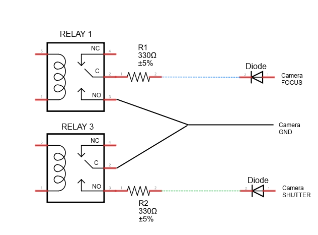
  constunsignedchar PS_128 = (1 << ADPS2) | (1 << ADPS1) | (1 << ADPS0);
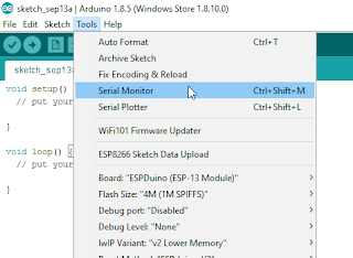


  //Setup()
  //===================================================================================================
  voidsetup(){
    //Initialise the Grove MP3 Module
    delay(2500); //Allow the MP3 module to power up
    mp3.begin(9600); //Begin Serial communication with the MP3 module
    setPlayMode(0x00);                        //0x00 = Single song - played once ie. not repeated. (default)
    
    //Define the Grove Button as an INPUT
    pinMode(buttonPin, INPUT);
    
    //Define the 4 LED Pins as OUTPUTs
    pinMode(8, OUTPUT); //Green LED
    pinMode(9, OUTPUT); //Blue LED
    pinMode(10, OUTPUT); //Red LED
    pinMode(11, OUTPUT); //Yellow LED
    
    //Make sure each LED is OFF, and store the state of the LED into a variable.
    for(int i=8;i<12;i++){
      digitalWrite(i, LOW);
      ledState[i-8]=0;
    } 
    
    //Double our clock speed from 125 kHz to 250 kHz
    ADCSRA &= ~PS_128;   // set up the ADC
    ADCSRA |= PS_64;    // set our own prescaler to 64
    
    //Create reference values to account for the capacitance of each pad.
    ref0 = ADCTouch.read(A0, 500);
    ref1 = ADCTouch.read(A1, 500); //Take 500 readings
    ref2 = ADCTouch.read(A2, 500);
    ref3 = ADCTouch.read(A3, 500);
    
     //This helps to randomise the drum pads.
     randomSeed(analogRead(0));
  }


  // Loop()
  //===================================================================================================
  voidloop(){
     
    //Take a reading from the Grove Sliding Potentiometer, and set volume accordingly
    potVal = analogRead(potPin);
    mp3Vol = map(potVal, 0, 1023, 0,31); // Convert the potentometer reading (0 - 1023) to fit within the MP3 player's Volume range (0 - 31)
    if((mp3Vol>(oldVol+1))|(mp3Vol<(oldVol-1))){ // Only make a change to the Volume on the Grove MP3 player when the potentiometer value changes
      oldVol = mp3Vol;
      setVolume(mp3Vol);
      delay(10); // This delay is necessary with Serial communication to MP3 player
    }
    
    //Take a reading from the Pin attached to the Grove Button. If pressed, randomise the MP3 songs/sounds for each drum pad, and make the LEDs blink randomly.
    buttonStatus = digitalRead(buttonPin);
    if(buttonStatus==HIGH){
      SongNum[0]=randomSongChooser(1, 30);
      SongNum[1]=randomSongChooser(31, 60);
      SongNum[2]=randomSongChooser(61, 86);
      SongNum[3]=randomSongChooser(87, (int)numOfSongs);
      randomLEDBlink();
    }
    
    //Get the capacitive readings from each drum pad: 50 readings are taken from each pad. (default is 100)
    int value0 = ADCTouch.read(A0,50); // Green drum pad
    int value1 = ADCTouch.read(A1,50); // Blue drum pad
    int value2 = ADCTouch.read(A2,50); // Red drum pad
    int value3 = ADCTouch.read(A3,50); // Yellow drum pad
    
    //Remove the offset to account for the baseline capacitance of each pad.
    value0 -= ref0;       
    value1 -= ref1;
    value2 -= ref2;
    value3 -= ref3;
    
    
    //If any of the values exceed the designated threshold, then play the song/sound associated with that drum pad.
    //The associated LED will stay on for the whole time the drum pad is pressed, providing the value remains above the threshold.
    //The LED will turn off when the pad is not being touched or pressed.
    if(value0>threshold){
      digitalWrite(8, HIGH);
      playSong(00,SongNum[0]);
    }else{
      digitalWrite(8,LOW);
    }
    
    if(value1>threshold){
      digitalWrite(9, HIGH);
      playSong(00,SongNum[1]);
    }else{
      digitalWrite(9,LOW);
    }
    
    if(value2>threshold){
      digitalWrite(10, HIGH);
      playSong(00,SongNum[2]);
    }else{
      digitalWrite(10,LOW);
    }
    
    if(value3>threshold){
      digitalWrite(11, HIGH);
      playSong(00,SongNum[3]);
    }else{
      digitalWrite(11,LOW);
    }
  }
      
   
  // writeToMP3:
  // a generic function that simplifies each of the methods used to control the Grove MP3 Player
  //===================================================================================================
  void writeToMP3(byte MsgLEN, byte A, byte B, byte C, byte D, byte E, byte F){
    byte codeMsg[] = {MsgLEN, A,B,C,D,E,F};
    mp3.write(0x7E); //Start Code for every command = 0x7E
    for(byte i = 0; i<MsgLEN+1; i++){
      mp3.write(codeMsg[i]); //Send the rest of the command to the GROVE MP3 player
    }
  }
  
  
  //setPlayMode: defines how each song is to be played
  //===================================================================================================
  void setPlayMode(byte playMode){
    /* playMode options:
          0x00 = Single song - played only once ie. not repeated.  (default)
          0x01 = Single song - cycled ie. repeats over and over.
          0x02 = All songs - cycled 
          0x03 = play songs randomly                                           */
    writeToMP3(0x03, 0xA9, playMode, 0x7E, 0x00, 0x00, 0x00);  
  }
  
  
  //playSong: tells the Grove MP3 player to play the song/sound, and also which song/sound to play
  //===================================================================================================
  void playSong(byte songHbyte, byte songLbyte){
    writeToMP3(0x04, 0xA0, songHbyte, songLbyte, 0x7E, 0x00, 0x00);            
    delay(100);
  }
  
  
  //setVolume: changes the Grove MP3 player's volume to the designated level (0 to 31)
  //===================================================================================================
  void setVolume(byte Volume){
    byte tempVol = constrain(Volume, 0, 31); //Volume range = 00 (muted) to 31 (max volume)
    writeToMP3(0x03, 0xA7, tempVol, 0x7E, 0x00, 0x00, 0x00); 
  }
  
  
  //randomSongChooser: chooses a random song to play. The range of songs to choose from
  //is limited and defined by the startSong and endSong parameters.
  //===================================================================================================
  byte randomSongChooser(int startSong, int endSong){
    randNumber = random(startSong, endSong);
    return((byte) randNumber);
  }
  
  
  //randomLEDBlink: makes each LED blink randomly. The LEDs are attached to digital pins 8 to 12.
  //===================================================================================================
  void randomLEDBlink(){
   counter=8;
   for(int i=0; i<40; i++){
     int x = constrain((int)random(8,12),8,12);
     toggleLED(x);
     delay(random(50,100-i));
   }
     
    for(int i=8;i<12;i++){
      digitalWrite(i, HIGH);
    }
    delay(1000);
    for(int i=8;i<12;i++){
      digitalWrite(i, LOW);
      ledState[i-8]=0;
    }
  }
  
  
  //toggleLED: is used by the randomLEDBlink method to turn each LED on and off (randomly).
  //===================================================================================================
  void toggleLED(int pinNum){
    ledState[pinNum-8]= !ledState[pinNum-8];
    digitalWrite(pinNum, ledState[pinNum-8]);
  }


Arduino Code Discussion

You can see from the Arduino code above, that it uses the ADCTouch library. This library was chosen over the Capacitive Sensing Library to eliminate the need for a high value resistor which are commonly found in Capacitive Sensing projects).
 
To increase the speed of the Analog readings, I utilised one of the "Advanced Arduino ADC" techniques described by Guy van den Berg on this Microsmart website.
 
The readings are increased by modifying the Arduino's ADC clock speed from 125kHz to 250 kHz. I did notice an overall better response time with this modification. However, the Grove Serial MP3 player is limited by it's inability to play more than one song or sound at a time. This means that if you hit another drum pad while the current sound is playing, it will stop playing the current sound, and then play the selected sound. The speed at which it can perform this task was quite impressive. In fact it was much better than I thought it would be. But if you are looking for polyphonic playability, you will be dissapointed.
 
This Serial MP3 module makes use of a high quality MP3 audio chip known as the "WT5001". Therefore, you should be able to get some additional features and functionality from this document. Plus you may find some extra useful info from the Seeedstudio wiki. I have re-used some code from the Arduino Boombox tutorial... you will find extra Grove Serial MP3 functions on that page.
 
I will warn you... the Grove Serial MP3 player can play WAV files, however for some reason it would not play many of the sound files in this format. Once the sounds were converted to the MP3 format, I did not look back. So if you decide to take on this project, make sure your sound files are in MP3 format, you'll have a much better outcome.
 
I decided to introduce a random sound selection for each drum pad to extend the novelty of this instrument, which meant that I had to come up with a fancy way to illuminate the LEDs. I demonstrated some of my other LED sequences on my instagram account. I sometimes use instagram to show my work in progress.
 
Have a look at the video below to see this project in action, and putting the Grove Serial MP3 player through it's paces.
 

The Video


First there was the Arduino Boombox, and now we have the Arduino Beatbox..... who knows what will come next !
 
Whenever I create a new project, I like to improve my Arduino knowledge. Sometimes it takes me into some rather complicated topics. There is a lot I do not know about Arduino, but I am enjoying the journey. I hope you are too !! Please Google plus one this post if it helped you in any way. These tutorials are free, which means I survive on feedback and plus ones... all you have to do is just scroll a little bit more and click that button :)


If you like this page, please do me a favour and show your appreciation :

 
Visit my ArduinoBasics Google + page.
Follow me on Twitter by looking for ScottC @ArduinoBasics.
I can also be found on Pinterest and Instagram.
Have a look at my videos on my YouTube channel.


However, if you do not have a google profile...
Feel free to share this page with your friends in any way you see fit.

Alcohol Detection Project

$
0
0

Please visit:
https://arduinobasics.blogspot.com
for original tutorial.


Description

'Tis the season to be jolly, but sometimes you would like to tone down the jolliness. Or perhaps you are the designated driver and need to know how festive that punch is !
I have the perfect solution for you:

The grove alcohol sensor.


Most people look to buy this sensor to make their own DIY breathalyser. Don't bother. You won't get the accuracy you are looking for, or you probably won't have all the necessary equipment/materials required to calibrate it. While you can get a rough idea, I would NOT recommend using this sensor to make any decisions based on quantitative measurements.

I will also point out that this sensor is not specific for Alcohol. It will react to some other chemicals too. In other words, you cannot assume that a positive result equates to the presence of alcohol (ethanol) in the air. It could be butane, LPG, Isopropanol etc etc.

This project will attempt to show how much alcohol is in the air, for the sole purpose of identifying the presence, as well as getting a rough estimate of the strength of alcohol, in a variety of festive drinks.

PLEASE NOTE:
Do not submerge the sensor in liquid, and avoid splashing the sensor. Also do not expose the sensor to strong chemicals (including alcohol) for extended periods. There is a 48 hour burn-in time for this sensor. Which means that it actually performs better once it has been used for over 48 hours. The sensor also needs to warm up, which often takes more than 15 minutes long. Once exposed to a strong concentration of alcohol in the air, the sensor takes what seems like an eternal amount of time to recover. Take this into consideration when planning your future project.


Parts Required

  1. Arduino Uno (or compatible board)
  2. Grove Base Shield (v2)
  3. Grove Alcohol Sensor
  4. Grove 16x2 LCD (White on Blue)
  5. Grove Universal 4 pin buckled cable: one supplied with each module.
  6. USB cable - to power and program the Arduino
  7. Battery pack / Power bank

More information about the Grove Modules can be found here:

The Grove Base shield has 14 pins on the Analog side, and 18 pins on the digital side. Check the number of pins on your Arduino UNO (or compatible board) to ensure the shield will sit nicely on top. NOT compatible with Arduino boards that have the Arduino Duemilanove pin header layout.


Arduino IDE

While there are many Arduino IDE alternatives out there, I would recommend that you use the official Arduino IDE for this project. I used the official Arduino IDE app (v1.8.5) for Windows 10.
Make sure to get the most up-to-date version for your operating system here.


Libraries required

The following libraries will be used in the Arduino code:

  1. Wire.h
  2. math.h
  3. rgb_lcd.h
The Wire.h library is used for I2C communication, for the Grove LCD screen.
The math.h library is used for the pow() function, to calculate the concentration of alcohol in the air.
The rgb_lcd.h library simplifies the operation of the LCD screen.
 
The Wire.h and math.h library are already within the Arduino IDE, no further download or installation required. However, you will need to install the rgb_lcd.h library - which can be downloaded from GitHub. Once you download the zip file, install it into the Arduino IDE:
  1. Load the Arduino IDE
  2. Navigate to Sketch >Include library > Add .ZIP library...
  3. Select the downloaded zip file from GitHub, and press the "Open" button
  4. Check that it installed correctly by navigating to File > Examples > Grove-LCD RGB Backlight


Arduino Code

If the Grove-LCD RGB Backlight option is available in the examples folder, then you are good to go.
 
Select File > New
 
Paste the following code into the Arduino IDE, and upload it to the Arduino UNO (or compatible board).
 
PLEASE NOTE: Make sure the Alcohol Sensor is NOT connected to the Arduino while uploading your code to the Arduino. It seems to interfere with Serial communication for some reason, and the renders the COM port unusable until you reset the board, reboot the IDE and/or your computer. The best way to avoid this issue, is to unplug the Alcohol sensor from the Grove Base shield, ANY time you upload code to the Arduino.


Connection instructions


Now that the code has been uploaded, it is now time to make the necessary connections from the Arduino to the Grove 16x2 LCD module, and also to the Grove Alcohol sensor.

  1. Disconnect the USB cable from the Arduino to remove power.
  2. Install the Grove Base Shield (v2) onto the Arduino UNO. The header pins on the Base shield should line up exactly with female headers of the Arduino. Please make sure that there are no stray or misaligned pins that are unaccounted for by the Arduino board.
  3. Set the Base Shield Switch to 5V. The switch is in the corner near the LED on the Base Shield.
  4. Connect one end of the 4-pin cable to A0 connector on the Grove Base Shield, and the other end of the cable to the Grove Alcohol Sensor module.
  5. Connect one end of a 4-pin cable to an I2C connector on the Grove Base Shield, and the other end of the cable to the Grove 16x2 LCD module.
  6. You can now apply power to the Arduino Board via the power jack or the USB cable.


Connection Table

Arduino to Grove Alcohol Sensor module

The Grove Alcohol sensor operates off 5V.
If you are using the Grove Base Shield, place the switch to 5V.
Disconnect the Alcohol sensor from the base shield when uploading code to the Arduino.


Arduino to Grove 16x2 LCD module

The Grove 16x2 LCD module can operate off 5V or 3.3V.
I used 5V from the Arduino UNO.


Project Explained

When the Arduino is powered up, you will be presented with a message, "Alcohol Project by ArduinoBasics". This is a splash screen to introduce the project.
 
The heater pin on the Alcohol sensor is then activated, which can cause the program to hang. If you do not see the message "Heater Activated", and only see a blank LCD screen - reset the Arduino board. There is a reset pin on the Base shield next to the LED. This message will only display for about 3 seconds before it starts to take readings from the Alcohol sensor.
 
I am guessing that each sensor is different, however, I found that the sensor worked best, once it had been in use for over 48 hours. I normally wait for the sensor reading to get above 5 or 6 before exposing it to alcohol fumes. You will notice the readings slowly increase over time. Wait until the readings stabalise, which can take anywhere between 15-20 minutes, or longer if the sensor has not been used for a while.


In the presence of alcohol fumes/vapour, the sensor readings will drop, and will trigger the Arduino to change the display to show the rough concentration of alcohol in the Air. Do not expose the sensor to strong concentrations of alcohol for extended periods, as this may permanently affect the sensor performance thereafter. I cannot tell you what readings are NORMAL, because I only have one sensor, and have nothing to compare it to. I have seen my sensor reading get to 11.96, but have noticed that the maximum reading changes each time I test it (sometimes higher, sometimes lower). I am guessing that the surrounding environmental conditions will affect this maximum (i.e. temperature / humidity / air quality), and also the length of time the sensor has had to "burn in" for.
 
Once you reach the maximum value (or as long as you are willing to wait), go ahead and test it out. Hover the sensor over the suspiciously alcoholic festive punch, and catch out your sneaky grandmother.


Conclusion

The biggest learning points for me about using the Grove Alcohol sensor, was how surprisingly long it took for the sensor to stabalise, and I guess how impatient I am. These types of sensors are often advertised as being a way to create your own breathalyser. But I quickly found out just how hard that was, and after my experience with the sensor, I would never contemplate using it for that purpose, because I cannot verify the accuracy of the results.
 
Can it detect alcohol in the air? Yes it can. The Grove Alcohol sensor can give a rough estimate of the concentration of alcohol vapour in the air, and at best, I would say that it gives you a semi-quantitative result. The same sensor will detect butane, LPG, petrol, isopropanol fumes - which is good or bad, depending on what you plan to use it for.


One of the most common ways of reading the Alcohol results is through the Serial monitor. However, the Alcohol sensor would for some reason lock up or freeze the Serial communication. I found the best way to observe readings from the Alcohol sensor was to use a Grove LCD module.
 
The Grove LCD module was very easy to use and enabled a more portable project. Grove modules are generally very easy to connect to the Grove Base shield, and are very much "plug and play". The Universal 4pin cables, reduce the "rats-nest" of wires - endemic to Arduino projects.
 
I hope this tutorial has helped you somewhat. If you use this project, please let me know your experience with it in the comments below, and even better, tell me who you caught out.  
 

If you found this tutorial helpful, please consider supporting me by buying me a virtual coffee.


Social Media

You can find me on various social networks:

Visit my ArduinoBasics Google + page.
Follow me on Twitter by looking for ScottC @ArduinoBasics.
I can also be found on Pinterest and Instagram.
Have a look at my videos on my YouTube channel.


Arduino Tutorials Discord Server

$
0
0
As you may be aware by now, Google+ is shutting down.
So in about a couple of months, it will no longer exist.

Many people within the Arduino community used Google+ to share their Arduino tutorials, and discuss various projects, and now they are all scrambling to find a suitable alternative.

Some of you may know that I created a community called "Arduino Tutorials" on Google+, and may be wondering where it will be going?

Good news, I have created a new Discord server to take it's place.

So if you would like to join a group of like-minded people who have varying levels of Arduino expertise (beginner to advanced), feel free to meet us there.

Oh, you will probably need this link to get there.
https://discord.gg/U96BpPe

See you soon,
I look forward to meeting you.

ScottC
Viewing all 112 articles
Browse latest View live