Quantcast
Channel: Arduino Basics
Viewing all 112 articles
Browse latest View live

Relay Module

$
0
0

WARNING: Mishandling or incorrect or improper use of relays could result in

  • serious personal injury or DEATH
  • possible physical damage of the product
  • faulty operation
  • or create serious/dangerous hazards.

Please make sure that you read and understand how your relay/relay module board works, the voltage and current it is rated for, and the risks involved in your project BEFORE you even attempt to start putting it together. Seek professional and qualified assistance BEFORE you undertake ANY high power projects.

If you choose to follow the instructions in this tutorial, you do so at your own risk. I am not an electrician, and am not a qualified electrical engineer - so please do your research and seek advice BEFORE undertaking a project using a relay. Please check your connections and test them BEFORE turning the power on.

I accept no responsibility for your project, or the risk/damage/fire/shock/injury/death/loss that it causes. You take full responsibility for your actions/project/creation, and do so at YOUR OWN RISK !!!

Please note: It is illegal in some countries to wire up a high power project without an electrician. Please check your country's rules/laws/regulations before you undertake your project. If you have any doubts - don't do it.


&nbsp

What is a relay

A Relay is an electrically operated switch. Many relays use an electromagnet to mechanically operate the switch and provide electrical isolation between two circuits. In this project there is no real need to isolate one circuit from the other, but we will use an Arduino UNO to control the relay. We will develop a simple circuit to demonstrate and distinguish between the NO (Normally open) and NC (Normally closed) terminals of the relay. We will then use the information gained in this tutorial to make a much more exciting circuit. But we have to start somewhere. So let's get on with it.

Parts Required:

Fritzing Sketch


Table of Connections


Arduino Sketch


  1
2
3
4
5
6
7
8
9
10
11
12
13
14
15
16
17
18
19
20
21
22
23
24
25
26
27
28
29
30
31
32
33
34
35
36
37
38
39
40
41
42
43
44
45
46


/* ===============================================================
      Project: 4 Channel 5V Relay Module
       Author: Scott C
      Created: 7th Sept 2014
  Arduino IDE: 1.0.5
      Website: http://arduinobasics.blogspot.com.au
  Description: Explore the difference between NC and NO terminals.
================================================================== */

 /*
  Connect 5V on Arduino to VCC on Relay Module
  Connect GND on Arduino to GND on Relay Module 
  Connect GND on Arduino to the Common Terminal (middle terminal) on Relay Module. */
 
 #define CH1 8   // Connect Digital Pin 8 on Arduino to CH1 on Relay Module
 #define CH3 7   // Connect Digital Pin 7 on Arduino to CH3 on Relay Module
 #define LEDgreen 4 //Connect Digital Pin 4 on Arduino to Green LED (+ 330 ohm resistor) and then to "NO" terminal on relay module
 #define LEDyellow 12 //Connect Digital Pin 12 on Arduino to Yellow LED (+ 330 ohm resistor) and then to "NC" terminal on relay module
 
 voidsetup(){
   //Setup all the Arduino Pins
   pinMode(CH1, OUTPUT);
   pinMode(CH3, OUTPUT);
   pinMode(LEDgreen, OUTPUT);
   pinMode(LEDyellow, OUTPUT);
   
   //Provide power to both LEDs
   digitalWrite(LEDgreen, HIGH);
   digitalWrite(LEDyellow, HIGH);
   
   //Turn OFF any power to the Relay channels
   digitalWrite(CH1,LOW);
   digitalWrite(CH3,LOW);
   delay(2000); //Wait 2 seconds before starting sequence
 }
 
 voidloop(){
   digitalWrite(CH1, HIGH); //Green LED on, Yellow LED off
   delay(1000);
   digitalWrite(CH1, LOW); //Yellow LED on, Green LED off
   delay(1000);
   digitalWrite(CH3, HIGH); //Relay 3 switches to NO
   delay(1000);
   digitalWrite(CH3,LOW); //Relay 3 switches to NC
   delay(1000);
 }


The Red light on the Relay board turns on when power is applied (via the VCC pin). When power is applied to one of the Channel pins, the respective green light goes on, plus the relevant relay will switch from NC to NO. When power is removed from the channel pin, the relay will switch back to NC from NO. In this sketch we see that power is applied to both LEDs in the setup() method. When there is no power applied to the CH1 pin, the yellow LED will be on, and the Green LED will be off. This is because there is a break in the circuit for the green LED. When power is applied to CH1, the relay switches from NC to NO, thus closing the circuit for the green LED and opening the circuit for the yellow LED. The green LED turns on, and the yellow LED turns off.

I also show what happens when you apply power to a channel (eg. CH3) when there is nothing connected to the relay terminals. The respective onboard LED illuminates. This is useful for troubleshooting the relays, and knowing what state the relay is in (NC or NO). NC stands for Normally closed (or normally connected) NO stands for Normally open (or normally disconnected)

Here is a circuit diagram for two of the relays on the relay module (CH1 and CH2).
This was taken from the iteadstudio site.


The Video


This tutorial will become very useful in the future. I now have an easy way of switching a circuit electronically. Yes, I could do this with a transistor, but sometimes it is nice to hear that mechanical click. I am not sure why I like relays, but I find them to be quite fun !!

If you liked this tutorial - please show your support :


Arduino Selfie

$
0
0


My attention is drawn towards the noise behind me....
I cannot believe it.
There it is.

  The Arduino is taking a SELFIE !!


How did this happen?
 
Well actually, it is not that difficult for an Arduino.
 
I found out that my Canon Powershot SX50 HS camera has a port on the side for a remote switch. In the "Optional Accessories" section of the camera brochure, it identifies the remote switch model as RS-60E3. I then looked up the model number on this website to find out the size of the jack (3 core, 2.5mm), and the pinout (Ground, focus and shutter) required to emulate the remote switch. Once I had this information, I was able to solder some really long wires to the jack and connect up the circuit (as described below).
 

And before I knew it, the Arduino was taking Selfies !!!

 
Warning : Any circuit you build for your camera (including this one) is at your own risk. I will not take responsibility for any damage caused to any of your equipment.
 

Parts Required:


Fritzing Sketch


Connection Table


Three core, 2.5 mm jack


Camera Connection to Relays


Jack pinout


Completed Circuit


Arduino Sketch


  1
2
3
4
5
6
7
8
9
10
11
12
13
14
15
16
17
18
19
20
21
22
23
24
25
26
27
28
29
30
31
32
33
34
35
36
37
38

/* ===============================================================
      Project: Arduino Selfie
       Author: Scott C
      Created: 14th Sept 2014
  Arduino IDE: 1.0.5
      Website: http://arduinobasics.blogspot.com/p/arduino-basics-projects-page.html
  Description: Arduino takes selfie every 30 seconds
================================================================== */

 /*
  Connect 5V on Arduino to VCC on Relay Module
  Connect GND on Arduino to GND on Relay Module */
 
 #define CH1 8   // Connect Digital Pin 8 on Arduino to CH1 on Relay Module
 #define CH3 7   // Connect Digital Pin 7 on Arduino to CH3 on Relay Module
 
 voidsetup(){
   //Setup all the Arduino Pins
   pinMode(CH1, OUTPUT);
   pinMode(CH3, OUTPUT);
   
   //Turn OFF any power to the Relay channels
   digitalWrite(CH1,LOW);
   digitalWrite(CH3,LOW);
   delay(2000); //Wait 2 seconds before starting sequence
 }
 
 voidloop(){
   digitalWrite(CH1, HIGH); //Focus camera by switching Relay 1
   delay(2000);
   digitalWrite(CH1, LOW); //Stop focus
   delay(100);
   digitalWrite(CH3, HIGH); //Press shutter button for 0.5 seconds
   delay(500);
   digitalWrite(CH3,LOW); //Release shutter button
   delay(30000); //Wait 30 seconds before next selfie
 }


By connecting up the camera to an Arduino, the camera just got smarter !!
The Arduino connects to 2 different channels on the relay board in order to control the focus and the shutter of the camera. The relays are used to isolate the camera circuit from that of the Arduino. I have also included a couple of diodes and resistors in the circuit as an extra precaution, however they may not be needed.

Warning : Any circuit you build for your camera (including this one) is at your own risk. I will not take responsibility for any damage caused to any of your equipment. Do your research, and take any precautions you see fit.


The Video


If you like this page, please do me a favour and show your appreciation :

  Visit my ArduinoBasics Google + page.
Follow me on Twitter by looking for ScottC @ArduinoBasics.
Have a look at my videos on my YouTube channel.


However, if you do not have a google profile...
Feel free to share this page with your friends in any way you see fit.

DIY Canon Intervalometer using Arduino

$
0
0


An intervalometer allows you to take photos at set intervals to view a slow process in super fast speed. Watching paint dry is just as boring in fast motion as it is at normal speed, however, when you point your camera to the clouds in the sky, you can get some amazing effects.
 
By taking a picture every 3 seconds, and then playing the sequence back at 30 frames a second, you will get to see a 10 minute event in just 7 seconds.To get a nice flowing motion picture, you need to get a good balance between the recording frame rate, and the play-back frame rate.
 

Clouds moving over city

 
The recording frame rate is limited by the amount of memory you have in your camera, the length of the captured event, battery charge, and the camera's general capabilities. The playback frame rate needs to be fast enough to prevent jittering, but not so fast that you lose the event in a blink of an eye. The more you practice with different subject matters, the more you get a feel for how long you need to keep the camera running and how long to leave between shots.
 
When taking pictures of the clouds, you can generally use a 3-5 second frame rate, depending on their speed across the sky. To capture the flow of traffic, I would recommend a picture every 1-2 seconds. However, for really slow events like a plant growing, you may need to extend the frame capture rate significantly. You will get a better idea once you try it for yourself.
 
 
City Traffic

 
This tutorial follows on from the Arduino selfie tutorial, so you might notice some similarities. However, in this tutorial, we will have more control over the intervalometer by using a sliding potentiometer and an LED bar. The pin layout is slightly different from the Arduino Selfie tutorial - so best to start from scratch to avoid pin misconfigurations.
 

Warning : Any circuit you build for your camera (including this one) is at your own risk. I will not take responsibility for any damage caused to any of your equipment.
 
I found out that my Canon Powershot SX50 HS camera has a port on the side for a remote switch. In the "Optional Accessories" section of the camera brochure, it identifies the remote switch model as RS-60E3. I then looked up the model number on this website to find out the size of the jack (3 core, 2.5mm), and the pinout (Ground, focus and shutter) required to emulate the remote switch. Once I had this information, I was able to solder some really long wires to the jack and connect up the circuit (as described below).
 
I use Time-Lapse tool to stitch all of the pictures together to create a movie/animation.
 
You will need to download and install the LED_Bar library from Seeedstudio into your Arduino IDE libraries folder in order to use the LED Bar in this tutorial. For more information about the LED Bar - visit the LED Bar Seeed-Studio wiki.
 

Parts Required:


Fritzing Sketch


Connection Tables


Arduino to Relay Module:


Relay Module to Camera:


Arduino to Slide Potentiometer:


Arduino to LED Bar:


Arduino Sketch


  1
2
3
4
5
6
7
8
9
10
11
12
13
14
15
16
17
18
19
20
21
22
23
24
25
26
27
28
29
30
31
32
33
34
35
36
37
38
39
40
41
42
43
44
45
46
47
48
49
50
51
52
53
54
55
56
57
58
59
60
61
62
63
64
65
66

/* ===============================================================
      Project: DIY Canon Intervalometer using Arduino
       Author: Scott C
      Created: 9th October 2014
  Arduino IDE: 1.0.5
      Website: http://arduinobasics.blogspot.com/p/arduino-basics-projects-page.html
  Description: Use Arduino as an intervalometer for Canon PowerShot SX50 HS
               A slide potentiometer is used to control the time between photos.
               The LED Bar is used to display the delay between photos.
               A 3 core 2.5mm jack is used to connect the Arduino and Relay module to the Camera.
================================================================== */

 /* You will need to download and install the LED_Bar library from here: https://github.com/Seeed-Studio/Grove_LED_Bar */
 #include <LED_Bar.h>

 /* Connect 5V on Arduino to VCC on Relay Module
    Connect GND on Arduino to GND on Relay Module */

 #define CH1 7   // Connect Digital Pin 7 on Arduino to CH1 on Relay Module
 #define CH3 6   // Connect Digital Pin 6 on Arduino to CH3 on Relay Module
 
 int potPin=A0; //Connect Slide potentiometer to Analog Pin 0 on Grove Base Shield
 int potValue=0; //The variable used to hold the value of the potentiometer

 LED_Bar bar1(9,8); //Connect LED Bar to Digital I/O 8 on Grove base shield.
                   //The LED Bar actually uses digital pin 8 and 9.

 voidsetup(){
   pinMode(CH1, OUTPUT);
   pinMode(CH3, OUTPUT);
   
   //Turn OFF any power to the Relay channels
   digitalWrite(CH1,LOW);
   digitalWrite(CH3,LOW);
   delay(2000); //Wait 2 seconds before starting sequence
   
   //Focus camera by switching Relay 1
   digitalWrite(CH1, HIGH);
   delay(2000);
   digitalWrite(CH1, LOW); //Stop focus
   delay(3000);
 }

 voidloop(){
      // Read the slide potentiometer and convert the reading to a value between 0 and 10.
      potValue=constrain(map(analogRead(potPin),0,1000,0,10),0,10);
      
      //Use the pot value to create a visual count-down display on the LED bar.
      for(int i = potValue; i>0; i--){
        bar1.setLevel(i);
        delay(1000);
      }
      
      //If the pot value is less than 1, then delay for 30 seconds.
      if(potValue<1){
        delay(30000);
      }
      
      //Turn LED Bar off when taking photo
      bar1.setLevelReverse(0);
      
      //Press shutter button for 0.1 seconds. Modify delay if required.
      digitalWrite(CH3, HIGH);
      delay(100);
      digitalWrite(CH3,LOW); //Release shutter button
 }


The Video


This project shows how to make your Canon Powershot SX50 HS a whole lot smarter using an Arduino. There are so many things that look so different with an intervalometer. While I connected a slide potentiometer to the Arduino to provide extra flexibility, and an LED Bar for visual feedback, there are many other sensors out there that can be combined with the camera. For example, you could use a PIR sensor to take a picture when movement is detected. Or take a picture when a laser trip-wire is broken. What about sound activation, light activation, leak detection.... the options are limitless.
 
This has been one of my favorite projects, it was a lot of fun, and very interesting.
I highly recommend that you try it out!


If you like this page, please do me a favour and show your appreciation :


Visit my ArduinoBasics Google + page.
Follow me on Twitter by looking for ScottC @ArduinoBasics.
Have a look at my videos on my YouTube channel.


However, if you do not have a google profile...
Feel free to share this page with your friends in any way you see fit.

One in a million

$
0
0
Just quietly - I am really happy that this blog has reached over 1 million page views!
I don't know what to say, but I feel like I should say something.

Thank you for visiting my blog.

Here are the blog posts that have received most attention to date:
1. Ultrasonic sensor
2. Simple Arduino Serial Communication
3. Bluetooth tutorial 1
4. Bluetooth Android Processing
5. Sound Sensor
6. 433 MHz RF Module with Arduino : this one is rising FAST !
7. Reading from a text file and sending to Arduino
8. Flex sensor and LEDs
9. PhotoCell - sensing light
10. Simple Arduino Serial Communication (Part 2)


For a list of all my projects - please visit my projects page:
ArduinoBasics Project Page

If that is not enough, then perhaps you should visit the Arduino Tutorials Community on Google+.
You are bound to find a project that sparks your interest, or perhaps you could even share your own !

Feel free to leave your thoughts, suggestions or messages in the comments.
Or if you wish to send a confidential message to me - then I would advise to use the form on my Feedback page.

Thanks again for visiting, and good luck with your project and/or Arduino journey !!

E-Paper Barcode 39

$
0
0

E-Paper (or Electronic paper) is a display technology that mimics the appearance of ordinary ink on paper. E-paper displays do not emit light, rather they reflect light, thus making them much more comfortable to read and provide a wider viewing angle than most light emitting displays (source: Wikipedia).

I printed something to an E-paper display, unplugged it, and could still read the message clearly months later. These E-paper displays are great for showing information that is static for long periods. You only need to provide power when the data or information needs updating.

Barcodes are used everywhere, and one of the simplest Barcodes to generate is the Code 39 format (also known as Code 3 of 9). I used an E-paper shield and E-paper module to display a number in this barcode format. I then tested it with a Barcode reader and it worked perfectly.
This tutorial will show you how to send a number to the Arduino from the Serial Monitor, and display the Barcode on the E-paper module.

Note: If you are using an Arduino UNO (or compatible), you will also need to get a micro SDHC card.
 

The Video


The video will show you how to assemble the shield and the module onto the Arduino, and also how to install the SDHC card.


Parts Required:

Library Download


To use the e-paper shield, you will need to download the Small e-paper Shield library.
This library will allow you to use the following functions on the e-paper shield:
  • begin : to set up the size of the e-paper panel
  • setDirection : to set up the display direction
  • drawChar : to display a Character at a specified position
  • drawString : to display a String of characters at a specified position
  • drawNumber and drawFloat : to display a number
  • drawLine : to draw a line
  • drawHorizontalLine : to draw a horizontal line
  • drawVerticalLine : to draw a vertical line
  • drawCircle : to draw a circle
  • fillCircle : to draw and fill a circle
  • drawRectangle : to draw a rectangle
  • fillRectangle : to draw and fill a rectangle
  • drawTriangle : to draw a triangle
You can also draw an image to the e-paper shield.

For more information on how to use these functions, please visit the seeedstudio wiki. If you are unfamiliar with installing libraries - then have a look at the following sites:

Barcode 39 Info

Barcode 39 (or Code 3 of 9) is a barcode that consists of black and white vertical lines. These lines can be thick or thin. Each character can be coded using 9 alternating black and white bars. The barcode always starts with a black bar, and ends with a black bar.

If you code using thin lines only, then each character can be coded using a total of 12 bars. A wide black line is essentially two thin black lines next to each other. Same goes for a wide white line. Because there are now only 2 options (black or white), you can create a binary code. I used a 1 for black bars, and 0 for white bars. If there was a thick black bar, then this would be represented with a 11. A thick white bar would be 00.

Each barcode sequence starts and ends with a hidden * character. Therefore if you were to display just the number 1, you would have to provide the code for *1*.

  • * = 100101101101
  • 1 = 110100101011
  • * = 100101101101
Notice that each character starts with a 1 and ends with a 1.
Something also to take note of: is that each character is separated by a thin white line (and not represented in the binary code).

All of these 0's and 1's can get a bit confusing, so I decided to represent these binary numbers as decimals. For example, the picture below shows how a 0 and an 8 would be coded (without the *):


The table below provides the binary and decimal codes for each number used in this tutorial. I have also included for your own reference, each letter of the alphabet, however I did not use these in this tutorial.

The binary representation of each character in this table was obtained from this site.
www.barcodeisland.com is a great resource of information about barcodes.

I adapted their binary code into a decimal equivalent, and therefore had to create my own table.


Arduino Sketch


  1
2
3
4
5
6
7
8
9
10
11
12
13
14
15
16
17
18
19
20
21
22
23
24
25
26
27
28
29
30
31
32
33
34
35
36
37
38
39
40
41
42
43
44
45
46
47
48
49
50
51
52
53
54
55
56
57
58
59
60
61
62
63
64
65
66
67
68
69
70
71
72
73
74
75
76
77
78
79
80
81
82
83
84
85
86
87
88
89
90
91
92
93
94
95
96
97
98
99
100
101
102
103
104
105
106
107
108
109
110
111
112
113


/* ===============================================================
      Project: Display Barcodes on an e-Paper Panel
       Author: Scott C
      Created: 6th January 2015
  Arduino IDE: 1.0.5
      Website: http://arduinobasics.blogspot.com/p/arduino-basics-projects-page.html
  Description: This project will allow you to send a number from the Serial 
               Monitor to the Arduino. The number will then be displayed on 
               the e-Paper panel as a Code-39 barcode (and text).
================================================================== */

#include <ePaper.h>
#include <SPI.h>
#include <SD.h>
#include "GT20L16_drive.h"

constint maxBarcodeSize = 10; // set the maximum barcode size to 10 digits
int barcode[maxBarcodeSize]; // initialise the barcode array to the maximum 10 digits
int barcodeText[maxBarcodeSize]; // initialise the barcodeText array to the maximum 10 digits
int barcodePos; // Used to identify each digit within the barcode
int barcodeLength; // Used to identify the actual length of the barcode

/*  The following array holds the decimal code for each digit (0-9). 
    Each digit can be converted to binary and then drawn as a barcode.
                         0     1     2     3     4     5     6     7     8     9         */
int barcodeDecimal[] = {2669, 3371, 2859, 3477, 2667, 3381, 2869, 2651, 3373, 2861};

int astrix = 2413; // "*" character decimal code used at beginning and end of barcode sequence


/*  When drawBarcode = "no", the program will not draw the barcode on the e-paper panel
    When drawBarcode = "yes", the command to draw the barcode on the e-paper panel will be triggered. */
String drawBarcode = "no";


/*  This variable is the x Position on the e-Paper panel screen */
int xPosition;


voidsetup(){
    Serial.begin(9600); // Initialise Serial communication
    EPAPER.begin(EPD_2_0); // Set the e-Paper panel size to 2 inches
    EPAPER.setDirection(DIRNORMAL); // Set the e-Paper panel display direction (to Normal)
    eSD.begin(EPD_2_0); // Prepares the SD card
    GT20L16.begin(); // Initialise the GT20L16 font chip on the e-Paper panel
    barcodePos = 0;                    // Set the barcode digit to the first digit in the barcode
    EPAPER.clear_sd(); // Clear the screen when starting sketch
    
    EPAPER.drawString("http://arduinobasics", 10, 20); //splash screen text
    EPAPER.drawString(".blogspot.com", 60, 40);
    
    EPAPER.display(); // Display the splash screen
}


voidloop(){
  
    // The Arduino will wait until it receives data from the Serial COM port
    
    while (Serial.available()>0){
      barcodeText[barcodePos] = Serial.read();
        
      if(barcodeText[barcodePos]>47 && barcodeText[barcodePos]<58){ // A number was sent
         barcode[barcodePos] = barcodeText[barcodePos]-48;            // Convert the decimal value from the serial monitor to a Number
      } 
      
      if(barcodeText[barcodePos]==46){ // If a "." is detected, then barcode is complete
        barcodeLength = barcodePos;                   // Set the length of the barcode (used later)
        drawBarcode = "yes"; // We can now draw the barcode
        
      }
      
      if(barcodePos>(maxBarcodeSize-1)){ // Check if maximum barcode length has been reached
       barcodeLength = barcodePos;                    // Set the length of the barcode (used later)
       drawBarcode = "yes"; // We can now draw the barcode
      }
     
       barcodePos++;                                  // Move to the next barcode digit
    }
    
    if(drawBarcode == "yes"){ // Only draw the barcode when drawBarcode = "yes"
      
      EPAPER.clear_sd(); // Clear the e-Paper panel in preparation for barcode
      xPosition = 15;                                 // Set the initial white-space on the left
      drawBCode(astrix, ''); // Each barcode starts with an invisible *
      
      for(int digit=0; digit<barcodeLength; digit++){ // Start drawing the barcode numbers
        drawBCode(barcodeDecimal[barcode[digit]], barcodeText[digit]);  // Call the drawBCode method (see below)
      }
      
      drawBCode(astrix, ''); // Each barcode ends with an invisible *
      EPAPER.display(); // Show the barcode image and text
      
      drawBarcode = "no"; // Stop it from drawing again until next barcode sequence sent
      barcodePos=0;                                   // Re-initialise the position back to first digit (in preparation for the next barcode)
    }
}


//The drawBCode method is the key method for drawing the barcode on the e-paper panel
void drawBCode(int bCode, char bCodeText){
  xPosition++;                                        // There is a white space between each digit
  for (int barPos = 11; barPos > -1; barPos--){ // Cycle through the binary code for each digit. Each digit is made up of 11 bars
    xPosition++;                                      // Advance the xPosition to draw the next bar (white or black)
    if(bitRead(bCode, barPos)==1){ // If the binary digit at this position is a 1, then draw a black line
      EPAPER.drawVerticalLine(xPosition, 10, 60); // This draws the individual Bar (black - only)
    }                                                 // If the binary digit is a 0, then it is left blank (or white).
  }
  EPAPER.drawChar(bCodeText, xPosition-9, 75); // Draw the human readable (text) portion of the barcode
}


There is something weird about the E-paper shield library which tends to display the word "temperature:" in the Serial monitor when opened, and with each serial transmission. Don't worry about this. Just ignore it.'


This tutorial shows you how to create your own renewable barcodes. While this only handles numbers at this stage, it could just as easily be upgraded to handle text as well. If you liked this tutorial, please give it a google+ thumbs up, share it with your friends, or just write a comment. Thankyou for visiting my blog.


If you like this page, please do me a favour and show your appreciation :

 
Visit my ArduinoBasics Google + page.
Follow me on Twitter by looking for ScottC @ArduinoBasics.
Have a look at my videos on my YouTube channel.


However, if you do not have a google profile...
Feel free to share this page with your friends in any way you see fit.

New forum

$
0
0
Hi everyone, I am trying something new. I have put a new forum page on this blog to help with project related questions. Sometimes the comments section of a project is not adequate for these queries, so I am trying out a new forum page to see if this helps or not. Let me know what you think, and if you have any suggestions, please let me know in the comments. ScottC

Weather Reporter - Temboo, Ethernet and Arduino

$
0
0


Arduino is well known for the large variety of sensors / modules that can be connected. It is quite easy to hook up a temperature or humidity sensor to get instant feedback about the surrounding environmental conditions. However, sometimes you do not have a temperature sensor. Sometimes you have a sensor, but would like to know the temperature in other cities ! Or you would like to know what the temperature will be tomorrow?

Well now you can !!

All you need is a Temboo account, an internet connection and the following components:

Parts Required


Project Description


An Arduino UNO (and Ethernet Shield) queries Yahoo using a Temboo account, and retrieves weather information. The data is filtered and processed, and then passed on to another Arduino UNO to be displayed on a TFT LCD module. Two Arduino UNOs are used because the Ethernet library and the UTFT library are both memory hungry, and together consume more memory than one Arduino UNO can handle. Yes - I could have used a different board such as the Arduino MEGA, but where is the fun in that ?? This project will teach you many things:
  • How to use an Ethernet Shield with a Temboo account to retrieve internet data
  • How to use a TFT LCD module (ITDB02-1.8SP)
  • How to reduce memory consumption when using the UTFT library
  • How to power two Arduinos with a single USB cable
  • How to transmit data from one Arduino to another (via jumper wires)
All of this and a whole lot more !!


Video

Have a look at the following video to see the project in action.


You will need to create a Temboo account to run this project:

Temboo Account Creation

Step 1:

Visit the Temboo website : https://www.temboo.com/ Create an account by entering a valid email address. Then click on the Sign Up button.


Step 2:

Verify your email address by clicking on the link provided in the email sent by Temboo. 

Step 3:

You will be directed to the account setup page: Create an Account Name, and Password for future access to your Temboo Account Check the terms of service and if you agree, then tick the box Press the Go! button


Step 4:

You will then encounter the "Welcome!" screen:


Step 5:

Navigate to the top right of the screen and select the LIBRARY tab


Step 6:

On the left hand side you will see a list of choreos. Type Yahoo into the search box on the top left of the screen. Navigate to the GetWeatherByAddress Choreo by clicking on...    Yahoo _ Weather _ GetWeatherByAddress


Step 7:

Turn the IoT Mode to ON (in the top right of screen)


Step 8:

What's your platform / device? : Arduino How is it connected? : Arduino Ethernet   The following popup box will appear:


Step 9:

Name: EthernetShield - you can choose any name. Letters and numbers only. No spaces. Shield Type: Arduino Ethernet MAC Address : You can normally find the MAC address of the Ethernet shield on the underside. Enter the MAC address without the hyphens. Then click SAVE.


Step 10:

Move to the INPUT section. Enter the Address of the place you want the Temperature for. Address = Perth, Western Australia Expand the Optional INPUT for extra functionality Units = c - If you want the temperature in Celcius.


Step 11:

This will automatically generate some Arduino CODE and a HEADER FILE. Don't worry about the Arduino code for now... because I will provide that for you. However, you will need the automatically generated HEADER file. I will show you what to do with that soon. So don't lose it !'


Temboo Library Install

The Temboo library will need to be installed before you copy the Arduino code in the sections below. To install the Temboo library into your Arduino IDE, please follow the link to their instructions:   Installing the Temboo Arduino Library  

UTFT Library Install

Download the UTFT library from this site: http://www.henningkarlsen.com/electronics/library.php?id=51 Once downloaded and extracted. Go into the UTFT folder and look for the memorysaver.h file. Open this file in a text editor, and "uncomment" all of the TFT modules that are not relevant to this project. I disabled all of the TFT modules except the last 3 (which made reference to ST7735) - see picture below. The TFT module we are using in this project is the ITDB02-1.8SP from ITEAD Studio. Save the memorysaver.h file, and then IMPORT the library into the Arduino IDE as per the normal library import procedure.  If you do not modify the memorysaver.h file, the Arduino SLAVE sketch will not compile.


Arduino Code (MASTER)

  This project uses 2 Arduino UNOs. One will be the Master, and one will be the Slave. The following code is for the Arduino MASTER.   Open up the Arduino IDE. (I am using Arduino IDE version 1.6) Paste the following code into the Arduino IDE code window.  PLEASE NOTE: You may need to change some of the lines to accomodate your INPUTS from step 10. Have a look around line 36 and 37. 
  1
2
3
4
5
6
7
8
9
10
11
12
13
14
15
16
17
18
19
20
21
22
23
24
25
26
27
28
29
30
31
32
33
34
35
36
37
38
39
40
41
42
43
44
45
46
47
48
49
50
51
52
53
54
55
56
57
58
59
60
61
62
63
64
65
66
67
68
69
70
71
72
73
74
75
76
77
78
79
80
81
82
83
84
85
86
87
88
89
90
91
92
93
94
95
96
97
98
99
100
101
102
103
104
105
106
107
108
109
110
111
112
113
114
115
116
117
118
119
120
121
122
123
124
125
126
127
128
129
130
131
132
132
133
134
135
136
137
138
139
140
141
142
143
144
145
146
147
148
149
150
151
152
153
154
155
156
157
158
159
160
161
162
163
164
165
166
167
168
169
170
171
172
173
174
175
176
177
178
179
180
181
182
183
184
185
186
187


/* ===============================================================================
      Project: Weather Reporter: Temboo, Ethernet, Arduino
        Title: ARDUINO MASTER: Get temperature from Yahoo using Temboo
       Author: Scott C
      Created: 27th February 2015
  Arduino IDE: 1.6.0
      Website: http://arduinobasics.blogspot.com/p/arduino-basics-projects-page.html
  Description: The following sketch was designed for the Arduino MASTER device. 
               It will retrieve temperature/weather information from Yahoo using your
               Temboo account (https://www.temboo.com/), which will then be sent to the
               Arduino Slave device to be displayed on a TFT LCD module.
               
   Libraries : Ethernet Library (that comes with Arduino IDE)
               Temboo Arduino Library - https://www.temboo.com/sdk/arduino
               
   Temboo Library installation instructions for Arduino: 
               https://www.temboo.com/arduino/others/library-installation

  You will also need to copy your Temboo Account information into a new tab and call it TembooAccount.h.
  Please follow the instructions on the ArduinoBasics blog for more information.
---------------------------------------------------------------------------------- */

#include <SPI.h>
#include <Dhcp.h>
#include <Dns.h>
#include <Ethernet.h>
#include <EthernetClient.h>
#include <Temboo.h>
#include "TembooAccount.h"// Contains Temboo account information - in a new tab.
#include <Wire.h>

byte ethernetMACAddress[] = ETHERNET_SHIELD_MAC; //ETHERNET_SHIELD_MAC variable located in TembooAccount.h
EthernetClient client;

String Address = "Perth, Western Australia"; // Find temperature for Perth, Western Australia
String Units = "c"; // Display the temperature in degrees Celcius

String ForeCastDay[7]; //String Array to hold the day of the week
String ForeCastTemp[7]; //String Array to hold the temperature for that day of week.

int counter1=0; //Counters used in FOR-LOOPS.
int counter2=0;

boolean downloadTemp = true; // A boolean variable which controls when to query Yahoo for Temperature information.


voidsetup() {
  Wire.begin(); // join i2c bus : Used to communicate to the Arduino SLAVE device.
 
  // Ethernet shield must initialise properly to continue with sketch.
  if (Ethernet.begin(ethernetMACAddress) == 0) {
    while(true);
  }
  
  //Provide some time to get both Arduino's ready for Temperature Query.
    delay(2000);
}


voidloop() {
  if (downloadTemp) {
    downloadTemp=false; //Stop Arduino from Querying Temboo repeatedly
    getTemperature();       //Retrieve Temperature data from Yahoo
    transmitResults();      //Transmit the temperature results to the Slave Arduino
  }
}


/* This function will Query Yahoo for Temperature information (using a Temboo account) */

void getTemperature(){
    TembooChoreo GetWeatherByAddressChoreo(client);

    // Invoke the Temboo client
    GetWeatherByAddressChoreo.begin();

    // Set Temboo account credentials
    GetWeatherByAddressChoreo.setAccountName(TEMBOO_ACCOUNT); //TEMBOO_ACCOUNT variable can be found in TembooAccount.h file or tab
    GetWeatherByAddressChoreo.setAppKeyName(TEMBOO_APP_KEY_NAME); //TEMBOO_APP_KEY_NAME variable can be found in TembooAccount.h file or tab
    GetWeatherByAddressChoreo.setAppKey(TEMBOO_APP_KEY); //TEMBOO_APP_KEY variable can be found in TembooAccount.h file or tab

    // Set Choreo inputs
    GetWeatherByAddressChoreo.addInput("Units", Units); // Set the Units to Celcius
    GetWeatherByAddressChoreo.addInput("Address", Address); // Set the Weather Location to Perth, Western Australia

    // Identify the Choreo to run
    GetWeatherByAddressChoreo.setChoreo("/Library/Yahoo/Weather/GetWeatherByAddress");

    // This output filter will extract the expected temperature for today
    GetWeatherByAddressChoreo.addOutputFilter("Temperature", "/rss/channel/item/yweather:condition/@temp", "Response");
    
    // These output filters will extract the forecasted temperatures (we need to know the day and temperature for that day)
    GetWeatherByAddressChoreo.addOutputFilter("ForeCastDay", "/rss/channel/item/yweather:forecast/@day", "Response");
    GetWeatherByAddressChoreo.addOutputFilter("ForeCastHigh", "/rss/channel/item/yweather:forecast/@high", "Response");

    // Run the Choreo;
    GetWeatherByAddressChoreo.run();

    //Reset our counters before proceeding
    counter1 = 0;
    counter2 = 0;
    
    while(GetWeatherByAddressChoreo.available()) {
      // This will get the first part of the output
      Stringname = GetWeatherByAddressChoreo.readStringUntil('\x1F');
      name.trim(); // get rid of newlines

      // This will get the second part of the output
      String data = GetWeatherByAddressChoreo.readStringUntil('\x1E');
      data.trim(); // get rid of newlines

      //Fill the String Arrays with the Temperature/Weather data
      if (name == "Temperature") {
        ForeCastDay[counter1] = "Today";
        ForeCastTemp[counter2] = data;
        counter1++;
        counter2++;
      }
      
      if(name=="ForeCastDay"){
        ForeCastDay[counter1] = data;
        counter1++;
      }
      
      if(name=="ForeCastHigh"){
        ForeCastTemp[counter2] = data;
        counter2++;
      }
    }
  
    //Close the connection to Temboo website
    GetWeatherByAddressChoreo.close();
  }


  /* This function is used to transmit the temperature data to the Slave Arduino */
  
  void transmitResults(){
    char tempData[10];
    int tempStringLength = 0;
    
    //Modify the current temp to "Now"
    ForeCastDay[0] = "Now";
    
    //Send * to Slave Arduino to prepare for Temperature Transmission
    Wire.beginTransmission(4); // Transmit to device #4 (Slave Arduino)
    Wire.write("*");
    delay(500);
    Wire.endTransmission();
    delay(500);
    
    //Send the temperatures on the Slave Arduino to be displayed on the TFT module.
    for (int j=0; j<20; j++){
      for (int i=0; i<6; i++){
        memset(tempData,0,sizeof(tempData));   //Clear the character array
        String tempString = String(ForeCastDay[i] + "," + ForeCastTemp[i] + ".");
        tempStringLength = tempString.length();
        tempString.toCharArray(tempData, tempStringLength+1);
        Wire.beginTransmission(4); // Transmit to device #4 (Slave Arduino)
        Wire.write(tempData);
        delay(1000);
        Wire.endTransmission();
        delay(4000);
      }
    }
    
    /* ----------------------------------------------------------------------
    // You can use this to send temperature results to the Serial Monitor.
    // However, you will need a Serial.begin(9600); statement in setup().
    
    Serial.println("The Current Temperature is " + ForeCastTemp[5] + " C");
    Serial.println();
    Serial.println("The Expected Temperature for");
    for (int i=0; i<5; i++){
      Serial.println(ForeCastDay[i] + " : " + ForeCastTemp[i] + " C");
    }
    ---------------------------------------------------------- */
  }


Select "New Tab" from the drop-down menu on the top right of the IDE. Name the file: TembooAccount.h

Paste the contents of the HEADER file from the Temboo webpage (Step 11 above) into the TembooAccount.h tab. If you do not have the TembooAccount.h tab with the contents of this HEADER file next to your Arduino Master sketch, then it will NOT work. 
Make sure to SAVE the Arduino Sketch and upload the code to the Arduino (MASTER)


Arduino Code (SLAVE)

  This project uses 2 Arduino UNOs. One will be the Master, and one will be the Slave. The following code is for the Arduino SLAVE.   Make sure to disconnect the Arduino MASTER from your computer, and keep it to one side. Connect the Arduino SLAVE to your computer, and upload the following code to it. Make sure to create a new sketch for this code (File _ New).  
  1
2
3
4
5
6
7
8
9
10
11
12
13
14
15
16
17
18
19
20
21
22
23
24
25
26
27
28
29
30
31
32
33
34
35
36
37
38
39
40
41
42
43
44
45
46
47
48
49
50
51
52
53
54
55
56
57
58
59
60
61
62
63
64
65
66
67
68
69
70
71
72
73
74
75
76
77
78
79
80
81
82
83
84
85
86
87
88
89
90
91
92
93
94
95
96
97
98
99
100
101
102
103
104
105
106
107
108
109
110
111
112
113
114
115
116
117
118
119
120
121
122
123
124
125
126
127
128
129
130
131
132
133
134
135
136
137
138
139
140
141
142
143
144
145
146
147
148
149
150
151
152
153
154
155
156
157
158
159
160
161
162
163
164
165
166
167
168
169
170
171
172
173
174
175
176
177
178
179
180
181
182
183
184
185
186
187
188
189
190
191
192
193
194
195
196
197


/* ===============================================================================
      Project: Weather Reporter: Temboo, Ethernet, Arduino
        Title: ARDUINO SLAVE: Display temperature on TFT LCD Module
       Author: Scott C
      Created: 27th February 2015
  Arduino IDE: 1.6.0
      Website: http://arduinobasics.blogspot.com/p/arduino-basics-projects-page.html
  Description: The following sketch was designed for the Arduino SLAVE device. 
               It will receive temperature information from the Arduino MASTER
               and then display this information on the ITDB02-1.8SP TFT LCD 
               Module. Please read the important notes below.

----------------------------------------------------------------------------------
NOTES:
This sketch makes use of the UTFT.h library from : 
http://www.henningkarlsen.com/electronics/library.php?id=51
Please note: You will need to modify the memorysaver.h file in the UTFT folder 
with a text editor to disable any unused TFT modules. This will save memory, 
and allow you to run this sketch on an Arduino UNO. I disabled all TFT modules in
that file except the last 3 (which made reference to ST7735).
I used a ITDB02-1.8SP TFT LCD Module from ITEAD Studio.
PinOut:

Arduino SLAVE      ITDB02-1.8SP TFT
         3.3V ---- VDD33
 Digital9 (D9)---- CS
 Digital8 (D8)---- SCL
 Digital7 (D7)---- SDA
 Digital6 (D6)---- RS
 Digital5 (D5)---- RST
          GND ---- GND
           5V ---- VIN

Usage: UTFT myGLCD(<model code>, SDA, SCL, CS, RST, RS);
Example: UTFT myGLCD(ITDB18SP,7,8,9,5,6);

-----------------------------------------------------------------------------------
This sketch also makes use of the Wire.h library. 
The Wire.h library comes with the Arduino IDE.
This enables communication between Arduino Master and Arduino Slave.
PinOut:

Arduino MASTER      Arduino SLAVE
   Analog4(A4) ---- Analog4 (A4) 
   Analog5(A5) ---- Analog5 (A5) 
           GND ---- GND

-----------------------------------------------------------------------------------
The Arduino Slave is powered by the Arduino Master:
PinOut:

Arduino MASTER      Arduino SLAVE
            5V ---- VIN

==================================================================================
*/

#include <UTFT.h>
#include <Wire.h>

//Declare all of the fonts
extern uint8_t SmallFont[];
extern uint8_t BigFont[];
extern uint8_t SevenSegNumFont[];

// Usage: UTFT myGLCD(<model code>, SDA, SCL, CS, RST, RS);
UTFT myGLCD(ITDB18SP,7,8,9,5,6);

boolean tempDisplay = false; //Helps with processing the data from the Arduino MASTER
boolean readTemp = false; //Helps to differentiate the day from the temperature values
String dayOfWeek=""; //Variable used to hold the Day of the Week
String tempReading=""; //Variable used to hold the Temperature for that day

String Units = "'C "; //Display Temperature in Celcius
String Address = "Perth, WA"; //Address to show at top of Display


voidsetup(){
  // Initialise the TFT LCD
  myGLCD.InitLCD();
  initialiseLCD();
  delay(5000);
  
  //Setup the Serial communication between the Arduino MASTER and SLAVE
  Wire.begin(4); // join i2c bus with address #4
  Wire.onReceive(receiveEvent); // register event
}


voidloop(){
  delay(50);
}


/*
  This function initialises the TFT LCD, and draws the initial screen.
*/
void initialiseLCD(){
  //Clear the screen
  myGLCD.clrScr();
  
  //Draw the borders (top and bottom)
  myGLCD.setColor(25, 35, 4);
  myGLCD.fillRect(0, 0, 159, 13);
  myGLCD.fillRect(0, 114, 159, 127);
  myGLCD.drawLine(0,18,159,18);
  myGLCD.drawLine(0,109,159,109);
  
  //Header and Footer Writing
  myGLCD.setColor(255, 255, 255);
  myGLCD.setBackColor(25, 35, 4);
  myGLCD.setFont(SmallFont);
  myGLCD.print("arduinobasics", CENTER, 1);
  myGLCD.print("blogspot.com", CENTER, 114);
}


/* This function executes whenever data is received from Arduino master
   It will ignore all data from the Master until it receives a '*' character.
   Once this character is received, it will call the receiveTemp() function
   in order to receive Temperature data from the Arduino Master.
*/
void receiveEvent(int howMany){
  if(tempDisplay){
    receiveTemp();
  }else{
    while(0 < Wire.available()){
      char c = Wire.read(); // receive byte as a character
      if(c=='*'){ // Searching for a '*' character
        tempDisplay=true; // If '*' received, then call receiveTemp() function
      }
    }
  }
}


/* This function is used to receive and process the Temperature data 
   from the Arduino Master and pass it on to the  displayTemp() funtion.
*/
void receiveTemp(){
  tempReading="";
  dayOfWeek = "";
  
  while(0 < Wire.available()){
    char c = Wire.read(); // receive byte as a character
    if(readTemp){
      if(c=='.'){ // If a . is detected. It is the end of the line.
        readTemp=false;
      }else{
        tempReading=tempReading+c;
      }
    }else{
      if(c==','){
      } else {
        dayOfWeek=dayOfWeek+c;
      }
    }
    if(c==','){
      readTemp=true;
    }
  }
  displayTemp();
}


/*
  Display the Temperature readings on the TFT LCD screen.
*/
void displayTemp(){
  //Clear the writing on top and bottom of screen
  myGLCD.setColor(25, 35, 4);
  myGLCD.fillRect(0, 0, 159, 13);
  myGLCD.fillRect(0, 114, 159, 127);
  
  //Small writing on top and bottom of screen
  myGLCD.setColor(255, 255, 255);
  myGLCD.setBackColor(25, 35, 4);
  myGLCD.setFont(SmallFont);
  myGLCD.print(Address, CENTER, 1);
  myGLCD.print(dayOfWeek, CENTER, 114);
  
  //Write the big temperature reading in middle of screen
  myGLCD.setBackColor(0, 0, 0);
  myGLCD.setFont(SevenSegNumFont);
  myGLCD.print(tempReading, CENTER, 40);
  
  //Write the Units next to the temperature reading
  myGLCD.setFont(BigFont);
  myGLCD.print(Units, RIGHT, 40);
}


Wiring it up

Once the code has been uploaded to both Arduinos (Master and Slave), I tend to label each Arduino so that I don't mix them up. You will notice an 'S' marked on the SLAVE in some of the photos/videos. Then it is time to piggy-back the shields onto the Arduinos and wire them up. Make sure you disconnect the USB cable from the Arduinos before you start doing this.


Step 1: Ethernet Shield

Place the Ethernet shield onto the Arduino MASTER. Connect an Ethernet cable (RJ45) to the Ethernet shield. The other end will connect to your internet router.


Step 2: Arduino SLAVE and TFT LCD module

 
You can either wire up the TFT LCD module on a breadboard, or you can use a ProtoShield with mini-breadboard. It doesn't really matter how you hook it up, but make sure you double check the connections and the TFT specifications before you power it up. I have powered the Arduino Slave by connecting it to the Arduino Master (see fritzing sketch below).  
There is no reason why you couldn't just power the slave seperately. In fact this is probably the safer option. But I read that this power-sharing setup was ok, so I wanted to give it a go. I have no idea whether it would be suitable for a long term power project... so use it at your own risk. I tried using 4 x AA batteries to power this circuit, but found that the LCD screen would flicker. So then I tried a 9V battery, and noticed that the 5V voltage regulator was heating up more than I felt comfortable with. In the end, I settled with the USB option, and had no further issues. I am sure there are other possible options, and feel free to mention them in the comments below.  
Use the following fritzing sketch and tables to help you wire this circuit up.  

Fritzing sketch


Arduino MASTER to SLAVE connection table


Arduino SLAVE to ITDB02-1.8SP TFT LCD


ITDB02-1.8SP TFT LCD Module Pictures


Project Pictures


If you like this page, please do me a favour and show your appreciation :

 
Visit my ArduinoBasics Google + page.
Follow me on Twitter by looking for ScottC @ArduinoBasics.
Have a look at my videos on my YouTube channel.


However, if you do not have a google profile...
Feel free to share this page with your friends in any way you see fit.

Arduino Boombox

$
0
0

Add sound or music to your project using the "Grove Serial MP3 Player".

An Arduino UNO will be used to control the Grove Serial MP3 player by sending it specific serial commands. The Grove Base Shield allows for the easy connection of Grove sensor modules to an Arduino UNO without the need for a breadboard. A sliding potentiometer, switch and button will be connected to the Base shield along with the Serial MP3 player. A specific function will be assigned to each of the connected sensor modules to provide a useful interface:

  • Sliding Potentiometer– Volume control
  • Button– Next Song
  • Switch– On/Off (toggle)
Once the MP3 module is working the way we want, we can then build a simple enclosure for it. Grab a shoe-box, print out your favourite design, and make your very own Arduino BOOMBOX!


Video

Watch the following video to see the project in action


Parts Required:

Optional components (for the BoomBox Enclosure):
  • Empty Shoe Box
  • Paper
  • Printer
  • Glue
If I had a 3D printer - I would have printed my own enclosure, but a shoebox seems to work just fine.
 

Putting it Together

Place the Grove Base shield onto the Arduino UNO,
and then connect each of the Grove Modules as per the table below.


If you do not have a Grove Base shield,
you can still connect the modules directly to the Arduino as per the table below:


When you are finished connecting the modules, it should look something like this:
  (ignore the battery pack):
 

As you can see from the picture above. You can cut holes out of the shoebox and stick the modules in place. Please ignore the battery pack, because you won't use it until after you have uploaded the Arduino code.


Arduino Sketch


  1
2
3
4
5
6
7
8
9
10
11
12
13
14
15
16
17
18
19
20
21
22
23
24
25
26
27
28
29
30
31
32
33
34
35
36
37
38
39
40
41
42
43
44
45
46
47
48
49
50
51
52
53
54
55
56
57
58
59
60
61
62
63
64
65
66
67
68
69
70
71
72
73
74
75
76
77
78
79
80
81
82
83
84
85
86
87
88
89
90
91
92
93
94
95
96
97
98
99
100
101
102
103
104
105
106
107
108
109
110
111
112
113
114
115
116
117
118
119
120
121
122
123
124
125
126
127
128
129
130
131
132
133
134
135
136
137
138
139
140
141
142
143
144
145
146
147
148
149
150
151
152
153
154
155
156
157
158
159
160
161
162
163
164
165
166
167
168
169
170
171
172
173
174
175
176
177
178
179
180
181
182
183
184
185
186
187
188
189
190
191
192
193


/* ===============================================================================
      Project: Grove Serial MP3 Player overview
       Author: Scott C
      Created: 9th March 2015
  Arduino IDE: 1.6.0
      Website: http://arduinobasics.blogspot.com/p/arduino-basics-projects-page.html

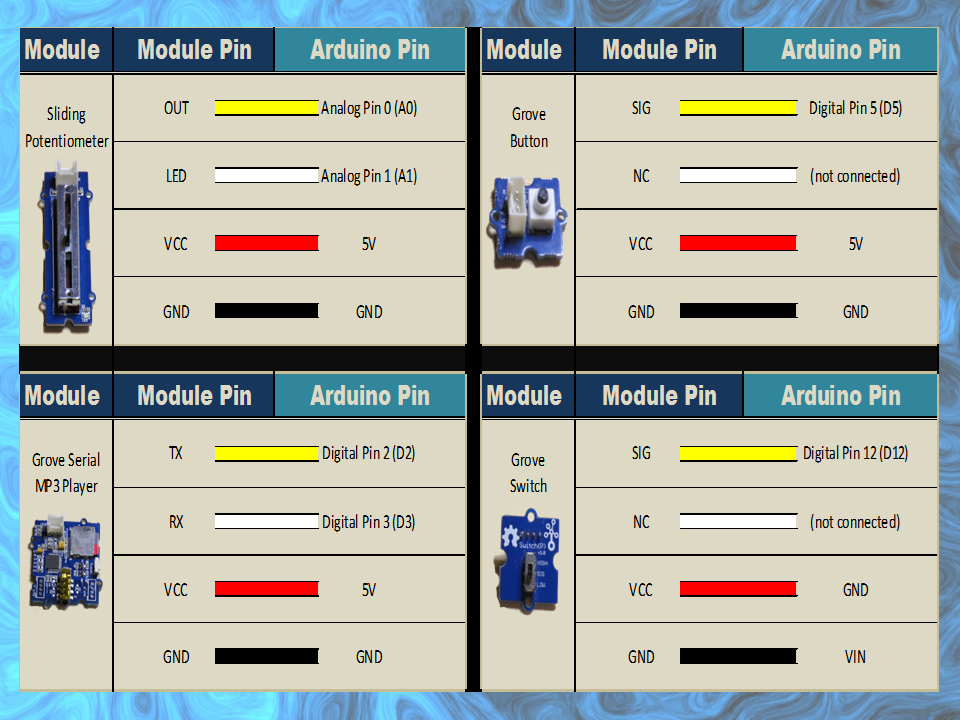
  Description: The following Arduino sketch will allow you to control a Grove Serial MP3 player
               with a Grove Sliding Potentiometer (volume), a Grove button (next song), 
               and a Grove Switch (on/off). It will also show you how to retrieve some useful information from the player. 
               Some functions are not used in this sketch,but have been included for your benefit. 
               
               Additional features and functionality can be found on the WT5001 voice chip datasheet 
               which I retrieved from here: http://goo.gl/ai6oQ9
               
               The Seeedstudio wiki was a very useful resource for getting started with the various Grove modules:
               http://goo.gl/xOiSCl
=============================================================================== */

#include <SoftwareSerial.h>
SoftwareSerial mp3(2, 3); // The Grove MP3 Player is connected to Arduino digital Pin 2 and 3 (Serial communication)
int potPin = A0; // The Sliding Potentiometer is connected to AnalogPin 0
int potVal = 0; // This is used to hold the value of the Sliding Potentiometer
byte mp3Vol = 0; // mp3Vol is used to calculate the Current volume of the Grove MP3 player
byte oldVol = 0; // oldVol is used to remember the previous volume level
int ledPin = A1; // The Grove sliding potentiometer has an onboard LED attached to Analog pin 1.

int switchPin = 12; // The Grove Switch(P) is connected to digital Pin 12
int switchStatus = 0; // This is used to hold the status of the switch
int switchChangeStatus = 0; // Used to identify when the switch status has changed

int buttonPin = 5; // The Grove Button is connected to digital pin 5
int buttonStatus = 0; // This is used to hold the status of the button


voidsetup(){
  //Initialise the Grove MP3 Module
  delay(2500);
  mp3.begin(9600);
  
        
  // initialize the pushbutton and switch pin as an input:
  pinMode(buttonPin, INPUT);
  pinMode(switchPin, INPUT);
  
  // set ledPin on the sliding potentiometer to OUTPUT
  pinMode(ledPin, OUTPUT);
  
  //You can view the following demostration output in the Serial Monitor
  demonstrate_GET_FUNCTIONS();     
}


voidloop(){
  switchStatus = digitalRead(switchPin);
  if(switchStatus==HIGH){
    if(switchChangeStatus==LOW){ // When Arduino detects a change in the switchStatus (from LOW to HIGH) - play song
      setPlayMode(0x02);                     // Automatically cycle to the next song when the current song ends
      playSong(00,01);                       // Play the 1st song when you switch it on
      switchChangeStatus=HIGH;
    }
    
    potVal = analogRead(potPin); // Analog read values from the sliding potentiometer range from 0 to 1023
    analogWrite(ledPin, potVal/4); // Analog write values range from 0 to 255, and will turn LED ON once potentiometer reaches about half way (or more).
    mp3Vol = map(potVal, 0, 1023, 0,31); // Convert the potentometer reading (0 - 1023) to fit within the MP3 player's Volume range (0 - 31)
    if((mp3Vol>(oldVol+1))|(mp3Vol<(oldVol-1))){ // Only make a change to the Volume on the Grove MP3 player when the potentiometer value changes
      oldVol = mp3Vol;
      setVolume(mp3Vol);
      delay(10); // This delay is necessary with Serial communication to MP3 player
    }

    buttonStatus = digitalRead(buttonPin);
    if(buttonStatus==HIGH){ // When a button press is detected - play the next song
      playNextSong();
      delay(200); // This delay aims to prevent a "skipped" song due to slow button presses - can modify to suit.
    }
  } else {
    if(switchChangeStatus==HIGH){ // When switchStatus changes from HIGH to LOW - stop Song.
      stopSong();
      switchChangeStatus=LOW;
    }
  } 
}


// demonstrate_GET_FUNCTIONS  will show you how to retrieve some useful information from the Grove MP3 Player (using the Serial Monitor).
void demonstrate_GET_FUNCTIONS(){
        Serial.begin(9600);
        Serial.print("Volume: ");
        Serial.println(getVolume());
        Serial.print("Playing State: ");
        Serial.println(getPlayingState());
        Serial.print("# of Files in SD Card:");
        Serial.println(getNumberOfFiles());
        Serial.println("------------------------------");
}


// writeToMP3: is a generic function that aims to simplify all of the methods that control the Grove MP3 Player

void writeToMP3(byte MsgLEN, byte A, byte B, byte C, byte D, byte E, byte F){
  byte codeMsg[] = {MsgLEN, A,B,C,D,E,F};
  mp3.write(0x7E); //Start Code for every command = 0x7E
  for(byte i = 0; i<MsgLEN+1; i++){
    mp3.write(codeMsg[i]); //Send the rest of the command to the GROVE MP3 player
  }
}


/* The Following functions control the Grove MP3 Player : see datasheet for additional functions--------------------------------------------*/

void setPlayMode(byte playMode){
  /* playMode options:
        0x00 = Single song - played only once ie. not repeated.  (default)
        0x01 = Single song - cycled ie. repeats over and over.
        0x02 = All songs - cycled 
        0x03 = play songs randomly                                           */
        
  writeToMP3(0x03, 0xA9, playMode, 0x7E, 0x00, 0x00, 0x00);  
}


void playSong(byte songHbyte, byte songLbyte){ // Plays the selected song
  writeToMP3(0x04, 0xA0, songHbyte, songLbyte, 0x7E, 0x00, 0x00);            
}


void pauseSong(){ // Pauses the current song
  writeToMP3(0x02, 0xA3, 0x7E, 0x00, 0x00, 0x00, 0x00);
}


void stopSong(){ // Stops the current song
  writeToMP3(0x02, 0xA4, 0x7E, 0x00, 0x00, 0x00, 0x00);
}


void playNextSong(){ // Play the next song
  writeToMP3(0x02, 0xA5, 0x7E, 0x00, 0x00, 0x00, 0x00);
}


void playPreviousSong(){ // Play the previous song
  writeToMP3(0x02, 0xA6, 0x7E, 0x00, 0x00, 0x00, 0x00);
}


void addSongToPlayList(byte songHbyte, byte songLbyte){
  //Repeat this function for every song you wish to stack onto the playlist (max = 10 songs)
  writeToMP3(0x04, 0xA8, songHbyte, songLbyte, 0x7E, 0x00, 0x00);
}


void setVolume(byte Volume){ // Set the volume
  byte tempVol = constrain(Volume, 0, 31);
  //Volume range = 00 (muted) to 31 (max volume)
  writeToMP3(0x03, 0xA7, tempVol, 0x7E, 0x00, 0x00, 0x00); 
}


/* The following functions retrieve information from the Grove MP3 player : see data sheet for additional functions--------------*/

// getData: is a generic function to simplifly the other functions for retieving information from the Grove Serial MP3 player
byte getData(byte queryVal, int dataPosition){
  byte returnVal = 0x00;
  writeToMP3(0x02, queryVal, 0x7E, 0x00, 0x00, 0x00, 0x00);
  delay(50);
  for(int x = 0; x<dataPosition; x++){
    if(mp3.available()){
      returnVal = mp3.read();
      delay(50);
    }
  }
  return(returnVal);
}

byte getVolume(){ //Get the volume of the Grove Serial MP3 player
  //returns value from 0 - 31
  return(getData(0xC1, 4));
}

byte getPlayingState(){ //Get the playing state : Play / Stopped / Paused
  //returns 1: Play, 2: Stop, 3:Paused
  return(getData(0xC2, 2));
}


byte getNumberOfFiles(){ //Find out how many songs are on the SD card
  //returns the number of MP3 files on SD card
  return(getData(0xC4, 3));
}

You will notice from the code, that I did not utilise every function. I decided to include them for your benifit. This Serial MP3 module makes use of a high quality MP3 audio chip known as the "WT5001". Therefore, you should be able to get some additional features and functionality from this document. Plus you may find some extra useful info from the Seeedstudio wiki.
 
IMPORTANT: You need to load your MP3 sounds or songs onto the SDHC card before you install it onto the Serial MP3 player.
 
Once the SDHC card is installed, and your code is uploaded to the Arduino, all you have to do now is connect the MP3 player to some headphones or a powered speaker. You can then power the Arduino and modules with a battery pack or some other portable power supply.
 
You can design and decorate the shoebox in any way you like. Just print out your picture, glue them on, and before you know it, you will have your very own Arduino Boombox.
 

Comments

I was very surprised by the quality of the sound that came from the MP3 module. It is actually quite good.

This tutorial was an introduction to the Grove Serial MP3 module in it's most basic form. You could just as easily use some other sensor to trigger the MP3 module. For example, you could get it to play an alert if a water leak was detected, or if a door was opened, or if the temperature got too high or too low. You could get it to play a reminder when you walk into your room. The possibilities are endless.

I really liked this module, and I am sure it will appear in a future tutorial.


If you like this page, please do me a favour and show your appreciation :

 
Visit my ArduinoBasics Google + page.
Follow me on Twitter by looking for ScottC @ArduinoBasics.
I can also be found on Pinterest and Instagram.
Have a look at my videos on my YouTube channel.


However, if you do not have a google profile...
Feel free to share this page with your friends in any way you see fit.


Arduino LED Light Box

$
0
0

Description

Long straight lines of LED luminescence is nice, but sometimes you may want to light up something that has an unusual shape, or is not so linear. This is where the 12mm diffused flat digital RGB LED Pixels can come into play. This cool strand of 25 RGB LED pixels fit nicely into 12mm pre-drilled holes of any material you like.

This tutorial is dedicated to making a LED Light Box. I wanted the box to be equally as interesting during the day as it was at night. If you decide you make your own, feel free to be as creative as you want !! However, if you lack artistic acumen, you may need to source a minion or two.


Arduino Libraries and IDE

Before you start to hook up any components, upload the following sketch to the Arduino microcontroller. I am assuming that you already have the Arduino IDE installed on your computer. If not, the IDE can be downloaded from here.

The FastLED library is useful for simplifying the code for programming the RGB LED pixels. The latest "FastLED library" can be downloaded from here. I used FastLED library version 3.0.3 in this project.

If you have a different LED strip or your RGB LED pixels have a different chipset, make sure to change the relevant lines of code to accomodate your hardware. I would suggest you try out a few of the FastLED library examples before using the code below, so that you become more familiar with the library, and will be better equipped to make the necessary changes.

If you have a single strand of 25 RGB LED pixels with the WS8201 chipset, then you will not have to make any modification below.


ARDUINO CODE:

Arduino Code Description

The code above will generate a randomised raindrop pattern on the Arduino LED Light box, however I have written code for a few more LED animations. These animations were written specifically for this light-box setup. In other words, once you have hooked everything up, you will be able to upload these other LED animations to the Arduino board without any further modification to the hardware/wiring, and yet experience a totally different light effect. You can find the code for the other animation effects by clicking on the links below:

  1. Breathing effect
  2. Ripple effect
  3. Clock effect
  4. Rotation effect
  5. Sweep effect
  6. Spiral effect
  7. Lightning effect
  8. Paparazzi in the Rain effect

Hooking it up:

Power requirements

Each LED pixel can draw up to 60 milliamps at maximum brightness (white). ie. 20 mA for each colour (red, green and blue). Therefore you should not try to power the LED strand directly from the Arduino, because the strand will draw too much current and damage the microcontroller(and possibly your USB port too). The LED strand will therefore need to be powered by a separate power supply. The power supply must supply the correct voltage (5V DC) and must also be able to supply sufficient current (1.5A or greater per strand of 25 LEDs).

Excessive voltage will damage or destroy your LED pixel strand. The LEDs will only draw as much current as they need, however your power supply must provide at least 1.5A or greater for each strand. If you chain two strands together, you will need a 5V 3A power supply.

RGB LED pixel strand connection

There are 25 LED pixels per strand. Four of the wires at each end of the strand are terminated with a JST connector. The red wire is for power (VCC), blue wire for ground (GND), yellow wire is for Data, and green wire for Clock. A spare red wire (VCC) and a spare blue wire (GND) are attached to the ends of each strand for convenience, however, I did not use either. Please double check the colour of your wires... they may be different.

If you want to attach the LED strand to a breadboard, you can cut the JST connector off and use the LED pixel strand wires. Alternatively, if you would prefer to preserve the JST connector, you can simply insert jumper wires (or some male header pins) into the JST connector, and then plug them into the breadboard as required.

Each LED pixel is individually controllable using two pins on your Arduino. The strand is directional. i.e. There is an INPUT side and an OUTPUT side. The strand should be connected such that wires from the microcontroller are attached to the INPUT side of the first LED pixel. The arrows on each LED show the direction of data flow from INPUT to OUTPUT. The arrow on the first LED pixel should be pointing towards the second LED pixel, NOT towards the breadboard.

Other considerations

As a precaution, you should use a large capacitor across the + and - terminals of the power supply to prevent the initial onrush of current from damaging the RGB LED pixels. I used a 4700uF 16V Electrolytic capacitor for this purpose. According to Adafruit, a 1000uF 6.3V capacitor (or higher) will also do the trick. You may also want to consider a 330 ohm resistor between the Arduino Digital pin and the strand's DATA pin.

If you want to power the Arduino using the regulated 5V external power supply. Disconnect the USB cable from the Arduino, and then connect the positive terminal of the power supply to the 5V pin on the Arduino. Be warned however, that excess voltage at this pin could damage your Arduino, because the 5V regulator will be bypassed.
 
Providing the USB cable is NOT connected to the Arduino, it should now be safe to plug the power supply into the wall. This setup will allow you to power the RGB LED pixel strand and the Arduino using the same power supply.
 
WARNING: Never change any connections while the circuit is powered.

For more information about these RGB LED pixel strands, you may want to visit the Adafruit site. Adafruit was the source for most of these RGB LED pixel Strand precautions.


Fritzing diagram

The following diagram demonstrates how to connect the RGB LED pixel Strand to the Arduino and to the External 5V power supply.


This diagram was created using Fritzing


Connection Instructions

These instructions will help to guide you through the process of connecting your RGB LED pixel strand to the Arduino, and to the external power supply. The instructions assume that you will be powering the Arduino via a USB cable.


LightBox assembly

You will need to drill a 12mm hole into the craft timber box for each LED on the strand. It is worth taking the time to make accurate measurements before drilling the holes.
 
I made 12 holes for the outside circle pattern (12cm diameter), 6 holes for the inside circle pattern (8cm diameter), and a hole in the centre. I also made two holes at the front of the box, two on the left side, and two on the right side. I made one last hole at the back of the box for the 2.1mm DC power line socket.
 
Therefore you should have a total of 26 holes in the box. 25 of the holes are for the RGB LED pixel LEDs and one for the external power supply socket.

The lid of the box is about 19.5cm x 14.5cm long, which makes for a very tight squeeze. Probably too tight, because you have to account for the inner dimensions of the box. The inside of the box is used to house the Arduino, breadboard, the chipset side of the LEDs and cables/components. The inner dimensions of the box are 18cm x 13cm. Therefore, the housing for the LED chipset PCB (1.8cm x 2.5cm) prevented the box from closing. I used a Dremel to carve out the space required to close the lid.

Each LED is approximately 8cm apart on the strand, however, if you are really keen, you could cut the wires and extend them to any distance you require. But keep in mind that each LED is mounted on a small PCB (with a WS2801 chipset).You will therefore need to leave a minimum of 2cm between each 12mm hole to accomodate the size of the PCB+LED. If you plan carefully, you can probably squeeze a couple of LEDs within a distance of 1cm... but I would recommend that you give yourself a bit more room, because the PCBs are not square, and there is a good chance that you will have to start all over again.

In hindsight, I could have made the circle patterns a bit smaller, however I don't know if I could have packed these LEDs any closer. The diameter of the inner circle pattern must be at least 2cm smaller than the outer circle pattern. So I think "a bigger box" would have been the best option.

Once all of the holes have been drilled, paint and decorate the box to suit your style.

When the paint is dry, insert the LEDs into the drilled holes in number order.
You can see the end result below.


Project Pictures

These pictures show the Light box after it has been drilled and painted. The LEDs have been inserted into their respective holes, and all wires + Arduino + breadboard are hidden within the box.


Concluding comments

Once you start writing LED animations for the RGB LED pixel Lightbox, it is very hard to stop. The colour combinations


If you like this page, please do me a favour and show your appreciation :

 
Visit my ArduinoBasics Google + page.
Follow me on Twitter by looking for ScottC @ArduinoBasics.
I can also be found on Pinterest and Instagram.
Have a look at my videos on my YouTube channel.


However, if you do not have a google profile...
Feel free to share this page with your friends in any way you see fit.

Generosity campaign - Day 1

$
0
0
How do you ask for support from the community without asking for money ?
I have no idea...........

But if you are feeling generous today, feel free to visit my generosity campaign 

... my long term quest to get a Digital Storage Oscilloscope :)

Indigogo has just launched their new site - Generosity.com for personal fundraising purposes.
There is no platform fee, however all processing charges will be deducted before any funds are paid out.

This new platform allows content creators like myself to do what they do best .... ie. create content.
And allows content consumers to support content creators and help them to become more "creative".


        Did I mention I had a long term quest to get a Digital Storage Oscilloscope ?


A while back, I started a Patreon page... but I didn't like the idea that people had to pledge per tutorial or per duration of time.... I mean, what if you did not like the tutorial or did not like the content in that month? Why should people have to pay for that? I guess one good thing about Patreon, is that it does encourage content creators to push out content on a more regular basis... 

Generosity.com on the other hand allows you to make a ONE TIME payment and walk away. And if you happen to like more content, you are free to walk up to that money jar as many times as YOU want... 

I know my campaign will go viral... and everyone will want to chip in to help me get an Oscilloscope :) .... Ok maybe not everyone...and I did say a  "long term" quest didn't I   ??

Hey, you could be the first one.... the person who donated first !!!
Everyone loves that person... the person who donated first !
And YOU could be that person!

But don't get too crazy... just do it quickly... you don't want to be the second person.
The second person is still loved, just not as much :)

Thank you for your generosity.


Generosity Campaign Update - Day 2

$
0
0
Well what a day it has been !! 


24 hours since the personal campaign to acquire 
a Digital Storage Oscilloscopewas launched... 
and it looks like everything is on track. 


Ok, maybe a bit slower than anticipated, but I think the idea to "spend money to support a content creator" is still sinking in... or maybe it is just sinking......Haha !!


Here are the stats so far...


After 24 hours, there were 43 people who paid a visit to see what this campaign was about, and I am pretty sure they ran out the virtual door to get their check books.... I eagerly await their return :)

Ok - so in total, after counting all the bills and all the change,


I have received a total contribution of 
$0 USD.


My total earnings for my entire site for that day when you include advertisements was:  $0.02


So from my calculations, the number of days until I will be able to afford an Oscilloscope, not accounting for inflation,  and also assuming the price of the Oscilloscope will remain the same is:


That time-frame is a bit hard to comprehend, so re-adjusting the calculation to years, I get this:


Ok - this is a bit slow... but the campaign is just warming up :)


I still believe that somewhere in the world 
someone will appreciate my work enough to 
donate one dollar (or more).... 


But what if no-one does???
That is ok...


I will still provide Arduino tutorials for FREE. 


I will just have to keep working harder to improve the quality of my tutorials, and have confidence in myself.
In fact I was very hesitant to put this campaign up. I did not know how well it would be received.


However, I wanted to go through the experience, to understand how the Generosity.com system worked.
And now if people feel inclined to provide a tip for my work, they are FREE to do so.

And you know what that tip will be spent on... yes - you guessed it..

a


I am not sure if anyone will read this page... or will even get down to this line on this page... but if you do... feel free to say hello in the comments - or recommend a good DSO to buy....Bear in mind though, it has to be a good brand/product -

the company still needs to be there in 63 years ... Haha !!

Hope you have a great day !!


Generosity Campaign Update - Day 3

$
0
0
Day 3:

Ok - I have now hit the 3rd day in the Generosity campaign.
This will be my last update of the campaign, unless something exciting happens.

It has been both a very interesting and lonely experience.

The bit that caught me off-guard and surprised me somewhat was the fact that there are opportunistic companies/people out there looking to make money from those not making money... does that make sense?

Let me give you an example.... after day1, there were $0 donations.
But my campaign did not go un-noticed.... I got a message telling me that my campaign could get a boost !!

How ?

Well, all I have to do is pay someone some money, and they will either generate some traffic, or market my campaign for me on various social media sites.... it will cost me $50 per tweet !!!!

No thanks !!!

Then I got another message, which told me that I could pay someone to donate a lesser amount to my campaign.... what the ???

The idea is that once people see that someone has already donated, they are more likely to donate. Like a restaurant... once you see other people enjoying a restaurant, you are more likely to choose that one, over the one that has no one in it.

I just couldn't do something like that... I find that deceptive.
If people want to donate, they will, and if they don't want to donate, well that is ok too.....

My blog has been active for a few years now - and my goal is simple.


Make Arduino tutorials 
- so that others don't have to go through the arduous process that I go through. 
Make them easy to read, easy to understand, and freely available,
for everyone to enjoy.


My money jar is here for anyone looking to find it.
Minimum donation = $1 USD

Am sorry - it defaults to $50, 
But you can change it to $1
The donation to Generosity.com is not compulsory - you can change that to $0


Two Million Views

$
0
0
My blog hit Two million views today !! Hooray !

And while I would love to celebrate this achievement, I think it is more important to remember that today is remembrance day.

Each year on this day Australians observe one minute's silence at 11am, in memory of those who died or suffered in all wars and armed conflicts.

Please stand for a minute silence - and remember those who have fallen before us.

#RemembranceDay


Get Arduino Data over the internet using jQuery and AJAX

$
0
0

Description

Have you ever wanted to transmit Arduino data over the internet?

In this tutorial, we will design a web page that will retrieve Analog readings from the Arduino's Analog Pins and display them on a bar chart within the web page.

The web page will use jQuery and AJAX to request the data from the Arduino Web Server, allowing us to update the bar chart dynamically, without having to refresh the entire web page. The Arduino Web Server will send the Analog readings to the web page in JSON format where it will be processed and displayed accordingly.

In this tutorial, I will not have anything connected to the Arduino's Analog pins, which means the data retrieved will be that of randomly floating analog pins. Feel free to connect a potentiometer, temperature sensor or any other analog sensor to these pins if you want to create a more "useful" project.

The main aim here was to show you how to transmit the data in JSON format, and to update only a portion of the web page using asynchronous communication (using AJAX), to improve the performance of data retrieval and visualisation.


Parts Required:

Please note: The WIZnet ioShield-A ver1.1 actually comes with the WIZ550io board. So if you buy the ioShield-A, you will receive both boards. I have provided the link to the WIZ550io shield because you can buy that shield on its own. Regardless, you will need to use both boards for this tutorial.


Arduino Libraries and IDE

To program the Arduino you will need to download the Arduino IDE, and install the WIZnet Ethernet Library. The Arduino IDE version used in this tutorial was version 1.6.4.
You may want to read the WIZnet wiki information for each WIZnet shield before use.


ARDUINO CODE:

Full description of the Arduino code is included in the YouTube video above. Once you have set up your Arduino Web Server, you should be able to ping it. Look at this website, if you don't know how to use the windows ping feature.


Getting the Arduino Board onto the internet:

There isn't anything really to hook up for this project. You just have to align the pins for each board and stack them. You can power the Arduino via the USB cable. This will also be useful for debugging and printing to the Serial monitor. An ethernet cable needs to connect the WIZ550io board's ethernet port to your internet/network router

  • The WIZ550io board goes on the top
WIZ550io Shield

  • The ioShield-A is in the middle
WIZnet ioShield-A ver 1.1

  • The Arduino UNO is on the bottom
Arduino UNO

  • This is what it looks like when they are stacked together
Arduino UNO plus ioShield-A plus WIZ550io shield

  • If you want to gain easy access to the Analog or digital pins without de-soldering the ioShield-A, you can introduce some female headers like this:
Arduino UNO with some extra Female headers

  • Please note that the ioShield-A utilises a number of pins on the Arduino UNO - including: D2, D4, D7, D10, GND, and IOREF, RESET, 5V, GND, GND and ICSP pins
  • All Analog pins are available for use


Set the Arduino Web Server on your local network

You can test this project on your local network. You just have to choose an available IP address and PORT within your router's IP range. If you don't know your local IP address range - you can have a look at this site to give you a helping hand.


Set the Arduino Web Server to be accessed from anywhere in the world

If you want to access your Arduino from anywhere in the world, you need to set up Port Forwarding on your internet network router. The following useful guides will hopefully get you on the right track, if you have never set up Port forwarding.


In my case, I programmed the Arduino UNO Web Server to take the following ip address on my internal network: 10.1.1.99

I programmed the Arduino Web Server to listen for Web Browsers on port 8081.
So if I wanted to connect to the Arduino Web Server through my home network, I just had to type in this web address into my web browser: http://10.1.1.99:8081

If you plan to connect to the Arduino using port 80 (which is the default port for web browsers), you can just type the IP address without specifying the port (eg. http://10.1.1.99/ )

The web browser should display the Arduino data in JSON format (the YouTube video above will show you what that looks like).

Once I knew I could connect to the Arduino in my internal network, I then set up port forwarding on my router so that I could type in my external IP address and special port to tunnel my way into my Arduino Web Server on my internal network. This is what I had to do on my router, but you may need to do something different.

  1. My first step was to find out my public/external IP address by typing "what is my IP address" into google. If you want to know your external IP address click here.
  2. I then typed my router's ip address into a web browser, and logged into my router.
  3. I went to the advanced settings tab
  4. Selected "Port Forwarding" from the side menu
  5. Filled out all of the details on the first line of the Ports list
    • Enable box = ticked
    • Description = Arduino
    • WAN interface = pppoe_atm0/ppp0
    • Inbound port = 8082
    • Type = TCP
    • Private IP address = 10.1.1.99
    • Private port = 8081
  6. Saved the settings

Now that I had port forwarding enabled, I could type the ip address (that I obtained in step 1) into my browser and specified port 8082 (instead of 8081) - eg. http://190.11.70.253:8082/

And now I can access my Arduino Web server from anywhere in the world. I can even access it from my smart phone. Once again, this will only return the Analog data in JSON format.

The Web Page GUI

The Arduino is now on the internet, so there are two options. You can either

Instructions on how to use these web pages, are listed below the HTML code.


To retrieve data from your Arduino Web Server, please make sure that it is connected and visible from outside of you local network. You will need to have port forwarding enabled. Information on port forwarding is described above.

  1. Find what your external IP address is.
  2. Enter this address using the IP address drop-down boxes within the "ArduinoBasics Webserver Data viewer" web page
  3. Enter the port forwarding port number (eg. 8082) into the box labelled "Port"
  4. Then click on the "Click here to start getting data" button - you should start to see the bar charts moving and status should be OK
  5. If the bar charts do not move, and the status message says "Failed to get DATA!!" - then the web page was unable to connect to the Arduino for some reason.

ArduinoBasics Web Data Viewer Web Page Example

Troubleshooting

  • You may want to type in the web address into your web browser, to make sure that data is being retrieved.
  • You can also open the Serial monitor in the Arduino IDE to make sure that an IP address is being displayed
  • Ensure that you have enabled the port forwarding option on your router
  • Have a look at Developer Tools within Google Chrome to help diagnose web page related issues.
  • The web page will not work properly if you use Internet Explorer or if you have javascript disabled within your browser.

Concluding comments

This tutorial showed you how to connect to your Arduino UNO over the internet, and retrieve data in JSON format using jQuery and AJAX. The web page can be modified to suit your own needs, plus it would be more useful if the Arduino was actually monitoring something, rather than logging data from floating pins. It would also be useful if the Arduino could be controlled to blink an LED, or to turn a motor... but I will leave that project for another day. I hope you enjoyed this tutorial - if it helped you in any way, please consider donating a small "tip" into my money jar. Thank you.


If you like this page, please do me a favour and show your appreciation :

 
Visit my ArduinoBasics Google + page.
Follow me on Twitter by looking for ScottC @ArduinoBasics.
I can also be found on Pinterest and Instagram.
Have a look at my videos on my YouTube channel.


However, if you do not have a google profile...
Feel free to share this page with your friends in any way you see fit.

Circuit Diagram

$
0
0
I just came across this site today (www.schematics.com).It looks pretty impressive !!
Schematics.com allows you to "build, share and view schematics from you browser"
You can also embed your schematic creations on your website - which is neat.


  Circuit Diagram - Schematics is the language of electronics. It provides a concise and comprehensive diagrammatic description of a circuit. Schematics.com allows users to connect and share designs and ideas in a like-minded community.


Arduino Stroboscope Animation

$
0
0


UPDATE: Magzor has just started a Kickstarter campaign. Please check it out to get a good package deal on many of their components. Many of which were used in this tutorial.
 
This tutorial will show you how to build your own Stroboscopic Animator using Magzor's Mechanotronic Design Portal as a starting point. Magzor Corporation is a business in California that is trying really hard to simplify robotic design. They want to enable users with little to no engineering experience to design and manufacture a custom robot by themselves in a matter of hours.
What is a stroboscope? A stroboscope is an instrument that uses a strobe light to make a moving object look stationary… We will use this feature to create an interesting 4 picture animation on a rotating disk.


Have a look at the video below to see the project in action, and the MDP process walk-through:


Video


Parts Required:


Magzor Schematic Diagram

Click to zoom ...

 
Further build instructions can be obtained by selecting the components in the Mechanotronics Design Portal within the Magzor website. Generating the build, and then selecting "Setup Instructions" tab at the top of the page. See video above to see this process in action.


Arduino Sketch


Make sure to copy and paste the following code into your Arduino IDE. It doesn't seem to work directly from the browser. You also need to install the Arduino Magzor I2C library ( http://magzor.com/downloads/ )


Putting it together


Arduino MEGA


Magzor I2C board


MIC Boards


MIC Boards Assembled


Sensors, Modules and Shields - all put together


Motor with Bracket and Wire


Picture lined up with magnet on disk


Stroboscopic Animation


The Arduino MEGA microcontroller listens for the hall effect sensor to be triggered by the south facing side of the magnet on the underside of the rotating disk. As the magnet moves over the hall effect sensor, the sensor is triggered and the Arduino instructs the LED to blink for a fraction of a second. By manipulating the delay after the trigger time, we can get the LED to blink when one of the four images on the rotating disk is towards the front position. And if we get the timing right, we can make a simple animation.
 
If you watch the video above, you will see that the image bounces around a little bit. The duration of each frame is determined by the speed of the rotating disk (or motor), and the number of LED flashes per frame. Any changes in rotation speed will affect the position of the picture when the LED blinks. My rotating disk is not completely semetrical or centred correctly, and therefore a bit jumpy… but you get the idea. Bold images with high contrast seem to work best… Precision is key for this type of project. And if you can get the disk to rotate at a constant speed, you could probably do away with the hall effect sensors and magnets… however, in my case, these were essential in getting the project to work as intended.
 
This project is a lot of fun. You can really get creative by making your own pictures or 3 dimensional models (for a stop motion effect). Try different colours. It really is quite cool.


Concluding Comments


I would like to thank Magzor for supplying the components used in this tutorial, and letting me try out their MDP process. I really like the concept, the one stop shop which looks after you from beginning to end. Providing everything I needed to get the project off the ground. The point of this exercise was to go through the entire process of selecting the parts, build the project, and get it up and running. And I have done that in no time at all.
 
There is only one library to download and install, and the good thing is that you don't have to go hunting for it. The latest "correct" working version of the library is easy to find, right there on the Magzor website… Speaking of the Magzor website, please make sure to take a quick look around. It is quite impressive.
 
  UPDATE: Magzor has just started a Kickstarter campaign. Please check it out to get a good package deal on many of their components. Many of which were used in this tutorial.


If you like this page, please do me a favour and show your appreciation :

 
Visit my ArduinoBasics Google + page.
Follow me on Twitter by looking for ScottC @ArduinoBasics.
I can also be found on Pinterest and Instagram.
Have a look at my videos on my YouTube channel.


This project would not have been possible without the collaborative effort from Magzor Corporation.
Please visit their site and check out the MDP.


However, if you do not have a google profile...
Feel free to share this page with your friends in any way you see fit.

Arduino Disco Ball Cake

$
0
0


Description

This is a fun project that will surely impress anyone you make this for. If you are having a "Disco" themed party, you cannot have a boring old cake. Let me tell you, this is probably the only Arduino project that my wife has ever been willing to be a part of. She did the hard work of putting the cake together, and I, well.... I was in charge of lighting. My biggest fear was that one of the wires would come loose and ruin the event at the most critical moment... While a wire did come loose, I managed to fix it in time before the guests arrived. Ok enough of my monologue, let me show you how to make one of these things.


Parts Required:


Arduino Libraries and IDE

You can get the Arduino IDE from here: https://www.arduino.cc/en/Main/Software
I used version 1.6.4, which is probably way out of date... but works fine nonetheless.
 
You can get information about how to use the FastLED library here: http://fastled.io/
And you can download it from here: FastLED Library
I used version 3.0.3, which is also probably out of date.

ARDUINO CODE:

ARDUINO CODE DESCRIPTION:

  • FastLED Library: You need to make sure that you have downloaded and installed the FastLED library into your Arduino IDE. The library is included in this sketch otherwise the FastLED functions will not work.
  • The "NUM_LEDS" variable: tells the Arduino how many LEDS are in use. In this case, we have 4 LED rings, with each LED ring containing 16 LEDs, and therefore a total of 64 LEDs. If you define a lower number, for example 16, then the sketch would only illuminate the LEDs on the first LED ring.
  • The "DATA_PIN" variable: tells the Arduino which Digital Pin to use for data transmission to the LED ring. In this case, I am using Digital Pin 9.
  • Other variables: I have a couple of other variables which are used for LED randomisation and hue control. Hue is the colour of the LED. By incrementing the hue variable, you can get the LEDs to cycle in a rainbow-like pattern. The "hue" variable is a "byte", which means that it will only go up to a maximum value of 255, before it jumps back down to zero.
  • Initialisation Code: If you have a different LED ring to the one in this tutorial, you may have to modify the initialisation code. This LED ring has a WS2812-B chipset (according to the ICStation website), and so this line:
     
    FastLED.addLeds(leds, NUM_LEDS); Will tell the FastLED library which chipset is being used (NEOPIXEL), the pin used for data transmission (DATA_PIN), the LED array to be controlled (leds), and the number of LEDs to be controlled (NUM_LEDS).
  • In the "loop()": section of the code: the "hue" variable is incremented to create a rainbow effect, and a random LED is selected using the FastLED's random8() function.
  • The random8(x) function: will randomly choose a number from 0 to x.
  • The randomSeed() function: is there to help "truely randomise" the number. This is helped by reading the randomness of a floating analogPin (A0). It doesn't have to be analogPin 0, it can be any unused analog pin.
  • leds[rnd].setHSV(hue,255,255): This line sets the random LED to have a hue equal to the "hue" variable, saturation equal to 255, and brightness equal to 255. Saturation equal to zero will make the LED shine white.
    Brightness of zero essentially turns the LED OFF.
  • FastLED.show(): No physical changes will be made to the LED ring display until a message is sent from the Arduino to the Digital input pin of the LED ring. This message is transmitted when you call the FastLED.show(); function. This tells the LED rings to update their display with the information contained within the led array (leds). So if you set all LEDs to turn on, the board will not illuminate the LEDs until the FastLED.show(); function is called. This is important to know - especially when trying to design your own LED sequences.
  • The delay(50) line: will set the amount of time between flashes to 50 milliseconds. You can change the delay to increase or decrease the number of flashes per second.
  • The leds[i].fadeToBlackBy( 180 ) function: essentially fades the LEDS by 180 units. You can increase or decrease this number to achieve the desired fade speed. Be warned however, that if you forget to call this function or if you fail to fade the LEDs sufficiently, then you may end up with ALL LEDs turning on, which could potentially destroy your Arduino board - i.e. depending on the number of LED rings you have, and how you have chosen to power them.


The Cake


  • Slide 1 - Base Plate: It is important to create the base plate with all of the electronics fitted and in working order BEFORE you put the Cake onto it. Trying to fit wires/cables LEDs and circuits under the base plate while there is a Cake ontop is a recipe for disaster. So prepare the base plate first, and then move to the cake making part later.
  • Slide 2 - Bake Cake: You will need a couple of hemisphere cake pans to make the two sides of the ball. You have to make a relatively dense cake to withstand the overall weight of the cake, icing and fondant, and to maintain it's shape. Once cooled and chilled, you can place them ontop of each other to form a sphere. They are held together by a layer of icing between them.
  • Slide 3 - Fondant Icing: The fondant icing has to be rolled out on a special non-stick mat. We found that adding a bit of flour helped to reduce the stickiness. There are special rollers which ensure that the thickness of the fondant is consistent throughout. You then have to cut them into square pieces (about 1 cm squares worked well for us). The squares are then painted Silver with a special/edible silver fondant glaze. You may need to use a few coats, and allowing it to dry between coats.
  • Slide 4 - Iced Cake on Base: The cake can either be iced on or off the base plate... probably better to do it off the base plate. But if you decide to do it on the base plate, you will need to protect the LEDs from stray icing that may fall from the cake (in the process). Once the cake has been fully iced (with icing/frosting), you will need to place the cake into the central position on the board. There may be a chance that the cake may slide from the base... so do what you need to do to make it stay put.
  • Slides 5-7 - Place Fondant Squares: While the icing is still soft, you will then need to quickly, methodically and tirelessly place the fondant squares in a horizontal linear pattern around the cake. Work your way towards the north and south poles of the cake doing one row at a time. You can cut a fondant circle for the north pole of the cake. In slide 7, you will see a hole at the top of the cake. This was made to cold a plastic canister inside, which would be used later the hold the decorations in place at the top of the cake. Do this before placing the fondant circle at the top of the cake.
  • Slide 8 - Add Glitter: After placing all of the fondant squares onto the cake, it is very possible that some of the Silver glaze may have been wiped off some of the squares. This is where you go over it again with a few more coats of silver glaze, and on the last coat, before it dries, you can sprinkle some edible glitter all around the cake to give it that extra shine.
  • Slide 9 - The end product: The final step is to add some wire sparklers and some other decorations to the top of the cake. Push the wires through the fondant cap at the north pole into the canister within. This will hold the wires in place without ruining all of your hard work.

LED Ring pins

  • WS2812-B chipset: This LED ring uses the WS2812-B chipset, and has 4 break-out pins
    (GND, 5V, Din, Dout)
  • Power: To power this module, you need to provide 5V and up to 1A of current
  • Signals: To control the LED ring, you need to send signals to it via the Digital Input pin (Din).
    You can connect another LED ring to this one by utilising the Digital Output pin (Dout)


Power Usage Guide

  • General Rule: Each individual LED on the ring can transmit Red, Green and Blue light.The combinations of these colours can make up any other colour. White light is made up of all three of these colours at the same time. Each individual colour will draw approximately 20mA of current when showing that colour at maximum brightness. When shining white at maximum brightness, the single LED will draw approximately 60mA.
  • Power multiplier: If each LED can draw up to 60mA and there are 16 LEDs on a single LED ring, then 16x60mA = 960mA per LED ring. To be safe, and to make the maths easier, you need to make sure that you provide enough current to accommodate 1A per LED ring. So 4 LED rings will need a 5V 4A power supply if you want to get full functionality out of the modules.


Fritzing diagram

Connecting ONE LED Ring to the Arduino- (Click to enlarge)


  • 3 wires: You only need 3 wires to connect to the LED ring. If you only plan to light up a couple of LEDs at any one time this should be ok.
  • The SAFE WAY: A safer way to do this is to use an external power supply to power both the Arduino and the LED ring.
  • Electrolytic capacitor: By connecting a large 4700 uF 16V Electrolytic capacitor between the positive and negative terminals of power supply leads, with the negative leg of the capacitor attached to the negative terminal of the power supply, you will protect your LED rings from any initial onrush of current.


  • Protecting Resistor: It is also advisable to place a 300-400 ohm resistor between the Arduino's Digital Pin 9 (D9) and the LED Ring's Digital Input pin (Din). This protects the first LED from potential voltage spikes
  • Suitable wires: If you plan to chain a few of these LED rings together (see below), then you will probably want to keep the wires as short as possible and use a decent guage wire that can handle the current being drawn through them.


Connecting TWO LED Rings to the Arduino- (Click to enlarge)


  • Three extra wires:You only need 3 extra wires to connect an additional LED ring. A wire needs to connect the Digital output (Dout) of the first LED ring to the Digital Input (Din) of the 2nd LED ring.
  • Stay safe: Once again, a safer way to do this is to use an external power supply, a large electrolytic capacitor at the terminals, and a 300-400 ohm resistor between the Arduino and the first LED ring's digital input pin.


Connecting FOUR LED Ring to the Arduino- (Click to enlarge)


  • Sixty Four LEDs:You need 3 extra wires for each additional LED ring. 4 LED rings provides a total of 64 LEDs.
  • Watch the AMPS:At full brightness, this setup could potentially draw up to 4amps (or roughly 1 amp per LED ring)
  • External Supply essential: It is essential to use an external power supply to power these LEDs when there are so many of them. If you don't use an external power supply and you accidentally illuminate ALL of the LEDs, then you are likely to damage the microcontroller from excessive current draw.

Connection Tables

How to connect ONE LED Ring to the Arduino- (Click to enlarge)


How to connect TWO LED Rings to the Arduino- (Click to enlarge)


Concluding comments

In this tutorial I showed you how to go about decorating a Disco Ball cake and also showed you how to use the RGB LED rings from ICStation. If you look at the video you will see just how versatile these LED rings are. I would like to thank my wife for providing such an exciting project to work on, and ICStation for their collaborative efforts. Please make sure to share this project with all of your friends and family.


If you like this page, please do me a favour and show your appreciation :

 
Visit my ArduinoBasics Google + page.
Follow me on Twitter by looking for ScottC @ArduinoBasics.
I can also be found on Pinterest and Instagram.
Have a look at my videos on my YouTube channel.

433 MHz RF module with Arduino Tutorial 3

$
0
0


There are 4 parts to this tutorial:

To get the most out of this tutorial - it is best to start at tutorial Part 1, and then progress to Part 2 then Part 3 and then do Part 4 last. Doing the RF tutorials in this order will help you to understand the process better.


Project 3: RF Remote Control Emulation

In the first tutorial, I introduced the 433 MHz Transmitter and Receiver with a simple sketch to test their functionality. In the second tutorial, the 433MHz receiver was used to receive a signal from an RF remote. The RF remote signal was coded based on the pattern and length of its HIGH and LOW signals. The signals received by the remote can be described by the code below:

 
Code comparison table


The RF remote that I am using transmits the same signal 6 times in a row. The signal to turn the light on is different from that used to turn the light off. In tutorial 2, we were able to "listen to" or receive the signal from the RF remote using the RF receiver. I thought it would be possible to just play back the signal received on the Arduino's analogPin, but the time it takes to perform a digital write is different to the time it takes to do an AnalogRead. Therefore it won't work. You need to slow down the digitalWrite speed.
I would like to find out if it is possible to apply this delay to all 433 MHz signal projects, however, I only have one 433 MHz remote.

If the delay in your project is the same as mine (or different) I would be keen to know - please leave a comment at the end of the tutorial.

We are going to use trial and error to find the optimal digitalWrite delay time. We will do this by slowly incrementing the delay until the transmission is successful. The transmission is considered successful if the fan-light turns on/off. All we have to do is count the number of transmissions until it is successful, then we should be able to calculate the delay.


Parts Required


The Transmitter Fritzing Sketch


RF Calibration - Arduino Sketch

 1
2
3
4
5
6
7
8
9
10
11
12
13
14
15
16
17
18
19
20
21
22
23
24
25
26
27
28
29
30
31
32
33
34
35
36
37
38
39
40
41
42
43
44
45
46
47
48
49
50
51
52
53
54
55
56
57
58
59
60
61
62
63
64
65
66
67
68
69
70
71
72
73
74
75
76
77
78
79
80
81
82
83
84
85
86
87
88
89
90
91
92
93
94
95
96
97
98
99
100
101
102
103
104
105
106
107
108
109
110
111
112
113
114
115
116
117
118
119
120
121
122
123
124
125
126
127
128
/* 
  Transmit sketch - RF Calibration
     Written by ScottC 17 July 2014
     Arduino IDE version 1.0.5
     Website: http://arduinobasics.blogspot.com
     Transmitter: FS1000A/XY-FST
     Description: A simple sketch used to calibrate RF transmission.          
 ------------------------------------------------------------- */

 #define rfTransmitPin 4  //RF Transmitter pin = digital pin 4
 #define ledPin 13        //Onboard LED = digital pin 13
 
 constint codeSize = 25; //The size of the code to transmit
 int codeToTransmit[codeSize]; //The array used to hold the RF code
 int lightON[]={2,2,2,2,1,4,4,4,4,5,1,4,4,4,4,4,4,5,2,2,1,4,4,4,6}; //The RF code that will turn the light ON
 int lightOFF[]={2,2,2,2,1,4,4,4,4,5,1,4,4,4,4,4,4,5,2,2,2,2,2,2,3}; //The RF code that will turn the light OFF
 int codeToggler = 0; //Used to switch between turning the light ON and OFF
 int timeDelay=5; // The variable used to calibrate the RF signal lengths.


 voidsetup(){
   Serial.begin(9600); // Turn the Serial Protocol ON
   pinMode(rfTransmitPin, OUTPUT); //Transmit pin is an output
   pinMode(ledPin, OUTPUT);
  
 //LED initialisation sequence - gives us some time to get ready
  digitalWrite(ledPin, HIGH);
  delay(3000);
  digitalWrite(ledPin, LOW);
  delay(1000);
 }


  voidloop(){
    toggleCode();    // switch between light ON and light OFF
    transmitCode();  // transmit the code to RF receiver on the Fan/Light
    
    timeDelay+=10;    //Increment the timeDelay by 10 microseconds with every transmission
    delay(2000); //Each transmission will be about 2 seconds apart.
  }


  /*----------------------------------------------------------------
     toggleCode(): This is used to toggle the code for turning 
                   the light ON and OFF 
  -----------------------------------------------------------------*/
  void toggleCode(){
    if(codeToggler){
       for(int i = 0; i<codeSize; i++){
         codeToTransmit[i]=lightON[i];
       } 
      
    } else{
      for(int i = 0; i<codeSize; i++){
         codeToTransmit[i]=lightOFF[i];
       } 
    }
    codeToggler=!codeToggler;
  }


  /*-----------------------------------------------------------------
    transmitCode(): Used to transmit the signal to the RF receiver on
                    the fan/light. There are 6 different HIGH-LOW signal combinations. 
                    
                    SH = short high   or  LH = long high   
                                     PLUS
         SL = short low    or    LL = long low    or    VLL = very long low
                    
  -------------------------------------------------------------------*/
   void transmitCode(){
    // The LED will be turned on to create a visual signal transmission indicator.
    digitalWrite(ledPin, HIGH);
   
   //initialise the variables
    int highLength = 0;
    int lowLength = 0;
    
    //The signal is transmitted 6 times in succession - this may vary with your remote.
    for(int j = 0; j<6; j++){
      for(int i = 0; i<codeSize; i++){
        switch(codeToTransmit[i]){
          case 1: // SH + SL
            highLength=3;
            lowLength=3;
          break;
          case 2: // SH + LL
            highLength=3;
            lowLength=7;
          break;
          case 3: // SH + VLL
            highLength=3;
            lowLength=92;
          break;
          case 4: // LH + SL
            highLength=7;
            lowLength=3;
          break;
          case 5: // LH + LL
            highLength=7;
            lowLength=7;
          break;
          case 6: // LH + VLL
            highLength=7;
            lowLength=92;
          break;
        }
           
         /* Transmit a HIGH signal - the duration of transmission will be determined
            by the highLength and timeDelay variables */
         digitalWrite(rfTransmitPin, HIGH);
         delayMicroseconds(highLength*timeDelay);
         
         /* Transmit a LOW signal - the duration of transmission will be determined
            by the lowLength and timeDelay variables */
         digitalWrite(rfTransmitPin,LOW);
         delayMicroseconds(lowLength*timeDelay);
      }
    }
    //Turn the LED off after the code has been transmitted.
    digitalWrite(ledPin, LOW);
 }
I used an array to hold the RF code for light ON and light OFF. Each number within the code represents a specific sequence of HIGH and LOW lengths. For example, 2 represents a SHORT HIGH and a LONG LOW combination. A short length = 3, a long length = 7, and a very long length = 92. You need to multiply this by the timeDelay variable to identify how much time to transmit the HIGH and LOW signals for.
The short and long lengths were identified from the experiments performed in tutorial 2 (using the RF receiver). Each code is transmitted 6 times. The LED is turned on at the beginning of each transmission, and then turned off at the end of the transmission. The timeDelay variable starts at 5 microseconds, and is incremented by 10 microseconds with every transmission.
In the video, you will notice that there is some flexibility in the timeDelay value. The Mercator Fan/Light will turn on and off when the timeDelay variable is anywhere between 75 and 135 microseconds in length. It also seems to transmit successfully when the timeDelay variable is 175 microseconds.
So in theory, if we want to transmit a signal to the fan/light, we should be able to use any value between 75 and 135, however in future projects, I think I will use a value of 105, which is right about the middle of the range.


Video


  Now that I have the timeDelay variable, I should be able to simplify the steps required to replicate a remote control RF signal. Maybe there is room for one more tutorial on this topic :)

Update: Here it is - tutorial 4
Where you can record and playback an RF signal (without using your computer).


433 MHz RF module with Arduino Tutorial 4:

$
0
0

WARNING: Please check whether you can legally use RF transmitters and receivers at your location before attempting this project (or buying the components). This project is aimed at those who are looking to automate their home.

There are 4 parts to this tutorial:

To get the most out of this tutorial - it is best to start at tutorial Part 1, and then progress to Part 2 then Part 3 and then do Part 4 last. Doing the RF tutorials in this order will help you to understand the process better.


Project 4 : 433 Mhz RF remote replacement tutorial

Carrying on from my previous "433MHz transmitter and receiver" tutorials (1,2&3): I have thrown away the need to process the signal with a computer. This means that we can now get the Arduino to record the signal from an RF remote (in close proximity), and play it back in no time at all.

The Arduino will forget the signal when powered down or when the board is reset. The Arduino does not have an extensive memory - there is a limit to how many signals can be stored on the board at any one time. Some people have opted to create a "code" in their projects to help maximise the number of signals stored on the board. In the name of simplicity, I will not encode the signal like I did in my previous tutorials.

I will get the Arduino to record the signal and play it back - with the help of a button. The button will help manage the overall process, and control the flow of code.

Apart from uploading the sketch to the Arduino, this project will not require the use of a computer. Nor will it need a sound card, or any special libraries. Here are the parts required:


Parts Required:

Fritzing Sketch


Arduino Sketch


  1
2
3
4
5
6
7
8
9
10
11
12
13
14
15
16
17
18
19
20
21
22
23
24
25
26
27
28
29
30
31
32
33
34
35
36
37
38
39
40
41
42
43
44
45
46
47
48
49
50
51
52
53
54
55
56
57
58
59
60
61
62
63
64
65
66
67
68
69
70
71
72
73
74
75
76
77
78
79
80
81
82
83
84
85
86
87
88
89
90
91
92
93
94
95
96
97
98
99
100
101
102
103
104
105
106
107
108
109
110
111
112
113
114
115
116
117
118
119
120
121
122
123
124
125
126
127


/* 
  433 MHz RF REMOTE REPLAY sketch 
     Written by ScottC 24 Jul 2014
     Arduino IDE version 1.0.5
     Website: http://arduinobasics.blogspot.com
     Receiver: XY-MK-5V      Transmitter: FS1000A/XY-FST
     Description: Use Arduino to receive and transmit RF Remote signal          
 ------------------------------------------------------------- */
 
 #define rfReceivePin A0     //RF Receiver data pin = Analog pin 0
 #define rfTransmitPin 4  //RF Transmitter pin = digital pin 4
 #define button 6           //The button attached to digital pin 6
 #define ledPin 13        //Onboard LED = digital pin 13
 
 constint dataSize = 500; //Arduino memory is limited (max=1700)
 byte storedData[dataSize]; //Create an array to store the data
 constunsignedint threshold = 100; //signal threshold value
 int maxSignalLength = 255; //Set the maximum length of the signal
 int dataCounter = 0; //Variable to measure the length of the signal
 int buttonState = 1; //Variable to control the flow of code using button presses
 int buttonVal = 0; //Variable to hold the state of the button
 int timeDelay = 105; //Used to slow down the signal transmission (can be from 75 - 135)

 voidsetup(){
   Serial.begin(9600); //Initialise Serial communication - only required if you plan to print to the Serial monitor
   pinMode(rfTransmitPin, OUTPUT);
   pinMode(ledPin, OUTPUT);
   pinMode(button, INPUT);
 }
 
 voidloop(){
   buttonVal = digitalRead(button);
  
   if(buttonState>0 && buttonVal==HIGH){
     //Serial.println("Listening for Signal");
     initVariables();
     listenForSignal();
   }
   
   buttonVal = digitalRead(button);
   
   if(buttonState<1 && buttonVal==HIGH){
     //Serial.println("Send Signal");
     sendSignal();
   }
   
   delay(20);
 }
 
 
 /* ------------------------------------------------------------------------------
     Initialise the array used to store the signal 
    ------------------------------------------------------------------------------*/
 void initVariables(){
   for(int i=0; i<dataSize; i++){
     storedData[i]=0;
   }
   buttonState=0;
 }
 
 
 /* ------------------------------------------------------------------------------
     Listen for the signal from the RF remote. Blink the RED LED at the beginning to help visualise the process
     And also turn RED LED on when receiving the RF signal 
    ------------------------------------------------------------------------------ */
 void listenForSignal(){
   digitalWrite(ledPin, HIGH);
   delay(1000);
   digitalWrite(ledPin,LOW);
   while(analogRead(rfReceivePin)<threshold){
     //Wait here until an RF signal is received
   }
   digitalWrite(ledPin, HIGH);
   
   //Read and store the rest of the signal into the storedData array
   for(int i=0; i<dataSize; i=i+2){
     
      //Identify the length of the HIGH signal---------------HIGH
      dataCounter=0; //reset the counter
      while(analogRead(rfReceivePin)>threshold && dataCounter<maxSignalLength){
        dataCounter++;
      }  
      storedData[i]=dataCounter;    //Store the length of the HIGH signal
    
      
      //Identify the length of the LOW signal---------------LOW
      dataCounter=0;//reset the counter
      while(analogRead(rfReceivePin)<threshold && dataCounter<maxSignalLength){
        dataCounter++;
      }
      storedData[i+1]=dataCounter;  //Store the length of the LOW signal
   }
   
     storedData[0]++;  //Account for the first AnalogRead>threshold = lost while listening for signal
     digitalWrite(ledPin, LOW);
 }
 
 
 /*------------------------------------------------------------------------------
    Send the stored signal to the FAN/LIGHT's RF receiver. A time delay is required to synchronise
    the digitalWrite timeframe with the 433MHz signal requirements. This has not been tested with different
    frequencies.
    ------------------------------------------------------------------------------ */
 void sendSignal(){
   digitalWrite(ledPin, HIGH);
   for(int i=0; i<dataSize; i=i+2){
       //Send HIGH signal
       digitalWrite(rfTransmitPin, HIGH);
       delayMicroseconds(storedData[i]*timeDelay);
       //Send LOW signal
       digitalWrite(rfTransmitPin, LOW);
       delayMicroseconds(storedData[i+1]*timeDelay);
   }
   digitalWrite(ledPin, LOW);
   delay(1000);
   
   
   /*-----View Signal in Serial Monitor
   for(int i=0; i<dataSize; i=i+2){
       Serial.println("HIGH,LOW");
       Serial.print(storedData[i]);
       Serial.print(",");
       Serial.println(storedData[i+1]);
   }
   ---------------------------------- */
 }


Now let's see this project in action !

Have a look at the video below to see the Arduino turning a light and fan on/off shortly after receiving the RF signal from the RF remote. The video will also show you how to put this whole project together - step by step.

The Video


This concludes my 433MHz transmitter and receiver tutorials (for now). I hope you enjoyed them.
Please let me know whether this worked for you or not.
I have not tested this project with other remotes or other frequencies - so would be interested to find out whether this technique can be used for ALL RF projects ??


If you like this page, please do me a favour and show your appreciation :

  Visit my ArduinoBasics Google + page.
Follow me on Twitter by looking for ScottC @ArduinoBasics.
Have a look at my videos on my YouTube channel.


However, if you do not have a google profile...
Feel free to share this page with your friends in any way you see fit.

Grove Water Sensor

$
0
0


Connecting a water sensor to an Arduino is a great way to detect a leak, spill, flood, rain etc. It can be used to detect the presence, level, volume and/or the absence of water. While this could be used to remind you to water your plants, there is a better Grove sensor for that. The sensor has an array of exposed traces which will read LOW when water is detected. In this tutorial, we will connect the Water Sensor to Digital Pin 8 on the Arduino, and will enlist the very handy Grove Piezo buzzer and an LED to help identify when the Water sensor comes into contact with a source of water.


Parts Required:

Putting it together


If you have a Grove Base Shield, you just have to connect the Grove Water Sensor to D8 on the shield, and the Buzzer to D12 on the Shield. My Grove base shield obstructs the onboard LED, so I will attach an LED to Digital pin 13. If you do not have a Grove base shield, then you should connect the Sensors as described in the tables below:


Arduino Sketch


  1
2
3
4
5
6
7
8
9
10
11
12
13
14
15
16
17
18
19
20
21
22
23
24
25
26
27
28
29
30
31
32
33


/* 
  Grove Water Sensor sketch 
     Written by ScottC 5th August 2014
     Arduino IDE version 1.0.5
     Website: http://arduinobasics.blogspot.com
     Description: Use Grove Water Sensor to detect leaks, floods, spills, rain etc.
     Credits: This sketch was inspired by this website:
              http://www.seeedstudio.com/wiki/Grove_-_Water_Sensor     
 ------------------------------------------------------------- */
#define Grove_Water_Sensor 8     //Attach Water sensor to Arduino Digital Pin 8
#define Grove_Piezo_Buzzer 12    //Attach Piezo Buzzer to Arduino Digital Pin 12
#define LED 13                   //Attach an LED to Digital Pin 13 (or use onboard LED)
voidsetup(){
pinMode(Grove_Water_Sensor, INPUT); //The Water Sensor is an Input
pinMode(Grove_Piezo_Buzzer, OUTPUT); //The Piezo Buzzer is an Output
        pinMode(LED, OUTPUT); //The LED is an Output
}

voidloop(){
        /* The water sensor will switch LOW when water is detected.
           Get the Arduino to illuminate the LED and activate the buzzer
           when water is detected, and switch both off when no water is present */
if(digitalRead(Grove_Water_Sensor) == LOW){
                digitalWrite(LED,HIGH);
digitalWrite(Grove_Piezo_Buzzer, HIGH);
                delay(2);
                digitalWrite(Grove_Piezo_Buzzer, LOW);
                delay(40);
        }else{
                digitalWrite(Grove_Piezo_Buzzer, LOW);
                digitalWrite(LED,LOW);
        }
}


The Video


If you liked this tutorial - please show your support :

Viewing all 112 articles
Browse latest View live