Quantcast
Channel: Arduino Basics
Viewing all 112 articles
Browse latest View live

Grove Infrared Universal Remote Project

$
0
0


Description

This project will convert an ordinary Keyes infra-red (IR) remote
into a programmable universal remote.

 
A single button press on the Keyes remote will be converted into precise Sony IR signal combinations using an Arduino UNO and an assortment of Seeedstudio Grove modules.
You can assign signal combinations from more than one remote if desired.
An example combination could be to:
  • Turn on the TV and then switch channels.
  • Turn on the TV, sound system, and air-conditioner.
  • Turn up the volume x 3.
With only one button press of the Keyes remote, the entire cascade of Sony signals ensues. This project can be customised for other IR methodologies, however, you may have to modify the Arduino code to accommodate them.


Parts Required

  1. Arduino Uno (or compatible board)
  2. Grove Base Shield (v2)
  3. Grove Infrared Receiver
  4. Grove Infrared Emitter
  5. Grove Button
  6. Grove 16x2 LCD (White on Blue)
  7. Grove Universal 4 pin buckled cable: one supplied with each module.
  8. KEYES IR Remote Control
  9. SONY IR remote control
  10. USB cable - to power and program the Arduino
  11. Battery pack / Power bank


More information about the Grove modules can be found here:

**Please Note: The Grove Base shield has 14 pins on the Analog side, and 18 pins on the digital side. Check the number of pins on your Arduino UNO (or compatible board) to ensure the shield will sit nicely on top. NOT compatible with Arduino boards that have the Arduino Duemilanove pin header layout.


Arduino IDE

While there are many Arduino IDE alternatives out there, I would recommend that you use the official Arduino IDE for this project. I used the official Arduino IDE app (v1.8.5) for Windows 10.
Make sure to get the most up-to-date version for your operating system here.


Libraries required

The following libraries will be used in the Arduino code:

  1. Wire Library
  2. IRLib2 Library
  3. rgb_lcd Library

Wire Library

The Wire library is used for I2C communication for the Grove LCD screen and is built into the Arduino IDE - no additional download required for this library.
 

IRLib2 Library

The IRLib2 Library is actually a "set" of IR libraries, which can be downloaded from GitHub - here. In this project, I will be transmitting and receiving NEC and Sony IR remote signals.
The required libraries (within the set) will be:
  • IRLibRecv.h
  • IRLibDecodeBase.h
  • IRLibSendBase.h
  • IRLib_P01_NEC.h
  • IRLib_P02_Sony.h
  • IRLibCombo.h
Please see the IRLib2 GitHub Page for installation instructions.
 

rgb_lcd Library

The rgb_lcd.h library simplifies the operation of the LCD screen.
Download the rgb_lcd.h library from GitHub. Install the rgb_lcd.h library ZIP file into the Arduino IDE:
  1. Load the Arduino IDE
  2. Navigate to Sketch >Include library > Add .ZIP library...
  3. Select the downloaded zip file from GitHub, and press the "Open" button
  4. Check that it installed correctly by navigating to File > Examples > Grove-LCD RGB Backlight


Arduino Code

It is always best to upload the Arduino code to the board before you make any of the connections. This way you prevent the Arduino from sending current to a component accidentally. The code is available on my GitHub repository. Or you can have a look below. This code was written for an Arduino UNO, and may need to be modified if you are using a different board.


Connection instructions

If you are using the Grove Base Shield (v2). The connections are extremely simple. Use the following table as a guide. Please note that the code above assumes the following connections.


As per the table above, you would use a Grove universal 4-pin buckled cable and connect one side to D2 on the Grove base shield, and the other side would connect to the Grove Infrared Emitter.
D3 on the base shield would connect to the Grove Infrared Receiver, and so on.
You can connect the 16x2 LCD module to ANY of the four I2C connectors on the Grove base shield.

If you do not have a Grove Base shield, you have the option to use female-to-male jumper wires (together with a breadboard). But it is easier just to get the base shield and use the universal connectors.


Project Explained

When you apply power to the Arduino, the first thing that appears on the LCD screen is:


After pressing the Grove button (connected to D5), it displays the following message:


This is the cue to press and send a signal from the Keyes remote to the Infrared receiver (which is connected to D2). The Arduino will decode the Keyes remote signal, store the value in an array, and display the signal briefly on the LCD. The LCD should now show a message:


This message is a cue to press and send the FIRST signal from the Sony remote to the Infrared receiver. The Arduino will decode and store the Sony remote signal in a different array, and display it briefly on the LCD. You have the option to send a maximum of THREE Sony signal combinations to the Infrared receiver at this step in the process. The minimum number of Sony signals you can send is zero. The way to tell the Arduino that you do not want to send any further Sony signals to the receiver in this step, is by pressing the Grove Button (connected to D5).
 
The Arduino is programmed to receive a total of 5 Keyes signals, and each signal can be paired with a maximum of 3 Sony signal combinations. Once you have recorded all of the signal combinations, you will get a message:


The Arduino will now enter the final "Universal remote mode". In this mode, it will listen out for ANY of the 5 Keyes IR remote signals recorded previously, and will send the associated Sony signal combination in return. For example, if you press the number 1 on the Keyes remote, you could potentially have it so that the Arduino will transmit a Sony signal combination to turn on the TV and jump to a specific channnel.
 
The LCD will display each of the signals being transmitted. You will know you are in "Universal remote" mode because the LCD will display:


While you may be tempted to throw your Sony remote away at this stage (because you no longer have a use for it)... I would hold on to it just in case. The signals are not stored permanently. They disappear when the Arduino is powered off. But it doesn't have to be that way. You can easily modify the code to store it in eeprom memory or something.
 
That is not the only thing you can change.Technically, you could record the signal for any remote, however, you may need to include additional libraries or code to accommodate the alternate remote symbology. You can also modify the text messages on the LCD screen to make more sense to you. The LCD can only display 16 characters per row. So keep that it mind, when you come up with creative captions.
 
I would also like to mention the reason I chose not to use Seeedstudio's IR library, was because it took up too much memory. Their library probably accommodates for a wide range of symbologies. I chose the IRLib2 Library because I could select only the symbologies that I used (Sony and NEC). Thereby reducing the total amount of memory necessary to run the project. In fact, I have been finding that many of Seeedstudio's libraries to be very memory hungry. I originally wanted to create a gesture controlled remote. But the library combinations eliminated that possibility due to the cumulative memory requirements.


Conclusion

The IRLib2 library is the key to the success of this project. Without that library, this project would have been ten times harder. I was quite amazed by the effectiveness of this record / playback technique. It felt very weird to be operating my SONY TV with a cheap and nasty Keyes remote. It was quite surreal. While I chose to control my TV in this way, I could have just as easily recorded signals from one of my other remotes that use infrared signals. As more and more devices become controllable by remotes, the more I will consider turning this project into a permanent fixture in my house. A gesture controlled remote would have been nice, however, it looks like I will have to find some other use for that module now.

If you found this tutorial helpful, please consider supporting me by buying me a virtual coffee/beer.

$3.00 AUD only
 

Social Media

You can find me on various social networks:

Follow me on Twitter: ScottC @ArduinoBasics.
I can also be found on Instagram, Pinterest, and YouTube.
And if all else fails, I have a server on Discord.


sprintf function

$
0
0
Original tutorial at: https://arduinobasics.blogspot.com/2019/05/sprintf-function.html


Description

This tutorial will help you to understand the sprintf function, and how to use it. Essentially, the sprintf function allows you to construct a string using a pre-formatted string template to which you can insert variables at pre-defined locations. The sprintf function will "compile" the string and assign it to a char array. All you have to do is make sure that the char array is large enough to hold all of the characters in the string. The best way to understand the sprintf function is with examples. And luckily, I have examples. What are we waiting for ? Let's dive in.

Parts Required: an Arduino and a USB cable.


sprintf ( char* array,   const char* strTemplate,   var1...);


Arduino IDE

While there are many Arduino IDE alternatives out there, I would recommend that you use the official Arduino IDE for this project. I used the official Arduino IDE app (v1.8.5) for Windows 10.
Make sure to get the most up-to-date version for your operating system here.


Arduino Code

The code below will show you how to use the sprintf function and includes a number of different format specifiers to play with. In each case the sprintf function writes to the "data" character array, and subsequently sends it through to the Serial monitor. The string template helps to construct the data output, allowing you to insert variables at specific locations within the text. The format of the variable is defined by the "format specifier" used in the sprintf function. The format specifier is always prefixed with a percentage sign (%).


Serial Monitor Output

  1. Upload the code to the Arduino.
  2. Open the Serial monitor in the Arduino IDE (Ctrl+Shift+M).
  3. Ensure that you have set the baud rate in the Serial monitor to 9600.
  4. You should see the following output:


The sprintf function requires that you have a character array to store the output. In the example code above, the output is stored in the "data" character array. It also requires a template that tells the function where to insert the variables. As you can see from the table below, the variables will be formatted based on the format specifier used. The format specifier can be quite useful for numeric conversions. Eg. decimal to hex conversions.


Format Specifiers

Some of the different format specifiers that can be used with the sprinf function are listed below.

Conclusion

Now that you know all about the sprintf function, I hope it will inspire you to use it in your own projects. Please let me know in the comments below how you use the sprintf function, and whether there was anything that you feel I failed to mention in this tutorial.
Happy Coding !!


If you found this tutorial helpful, please consider supporting me by buying me a virtual coffee/beer.

$3.00 AUD only
 

Social Media

You can find me on various social networks:

Follow me on Twitter: ScottC @ArduinoBasics.
I can also be found on Instagram, Pinterest, and YouTube.
And if all else fails, I have a server on Discord.


Maker Display to Ubidots MQTT button

$
0
0

See the original project on the ArduinoBasics Blog


Description

This tutorial will show you how to create a simple MQTT connection to Ubidots. You will also learn to configure the necessary MQTT subscription to a button on the Ubidots dashboard, and control a Maker Display (ESP-12E compitible board) from anywhere in the world. The process may seem a bit daunting at first, but hopefully by the end of this tutorial, you will feel comfortable creating your own Ubidots MQTT subscriptions.


Parts Required

  1. Maker Display 2 or Node MCU (ESP-12E) module
  2. NOVA programmer
  3. USB mini-B cable
  4. WiFi internet connection
  5. Ubidots account (free)

The Maker display 2 has an inbuilt ESP8266MCD WiFi module which will be used to create the MQTT connection to the Ubidots broker (online).


Ubidots Setup

This tutorial requires a FREE Ubidots account.
Go to this site to sign up: https://ubidots.com/education/
Once signed up, you will need to configure Ubidots using the following instructions.

Create a device

  1. Select: Devices > Devices
  2. Select: Create a Device (button)
  3. Select: Blank (from the available device list)
  4. Enter the "Maker Display" into the "Device name" field, "maker-display" into the "Device label" field, and click on "Create" button
  5. Select: the "Maker Display" device

Create a variable

  1. Select: "Add Variable" button, then select "Raw" from the two available options.
  2. Select: the "New Variable" to edit it
  3. Change the name to "Button 1", the description to "button1 variable" and the API label to "button1"

Create a dashboard

  1. Select: Data > Dashboard
  2. Select: Add new dashboard
  3. Change the Name to "Maker Display Dashboard", and update the date format to a suitable format. (press tick)

Add a Widget

  1. Select: "Add new Widget"
  2. Select: Switch (from the available widgets)
  3. Select: Add Variables
  4. Select: Maker Display > Button1 > tick
  5. Accept the default values for the Switch (Off=0, On=1), and press the tick
  6. You should now have a button called "Button1" associated with the "Maker Display" device, visible on the "Maker Display Dashboard"
  7. The button is "off".

Create a Ubidots TOKEN

  1. Select: "API Credentials" from the profile drop-down box in the top right corner.
  2. Click the blue "More" - located below the Tokens section
  3. Click on the round blue (+) button to create a NEW TOKEN.
  4. Change the name to "Maker Display Token" - and keep a record of TOKEN value. There is an icon which will allow you copy the TOKEN value to the clipboard.

Take note of key information

Now that the Ubidots Dashboard is set up, you will need to ensure you have 3 sets of information to insert into the code.

  1. Maker Display Token Value
  2. Button1 API label: "button1"
  3. Maker Display Device API Label: "maker-display"


Ubidots slideshow of the setup process

Slide Set created by Scott C with GoConqr


Arduino IDE

While there are many Arduino IDE alternatives out there, I would recommend that you use the official Arduino IDE for this project. I used the official Arduino IDE app (v1.8.5) for Windows 10.
Make sure to get the most up-to-date version for your operating system here.

Additional Boards Manager URLS

Make sure to add the following URLs to your "additional boards manager URL" setting:
  • File > Preferences > Additional Boards Manager URLS:
    • http://arduino.esp8266.com/stable/package_esp8266com_index.json
    • https://dl.espressif.com/dl/package_esp32_index.json

Select Tools > Board: "NodeMCU 1.0 (ESP-12E Module)" board.
Then check that you have the following settings:

  • Board:"NodeMCU 1.0 (ESP-12E Module)"
  • Flash Size:"4M(no SPIFFS)"
  • Debug port:"Disabled"
  • Debug Level:"None"
  • IwIP Variant:"v2 Lower Memory"
  • VTables:"Flash"
  • CPU Frequency:"80 MHz"
  • Exceptions:"Disabled"
  • Upload Speed:"115200"
  • Erase Flash:"Only Sketch"
  • Port: (Select your port)
  • Get Board Info
  • Programmer:"AVRISP mkII"


Libraries required

This tutorial makes use of two libraries: ESP8266WiFi.h and PubSubClient.h.

  • ESP8266WiFi.h : This library is required for the WiFi connection to the internet. More info.
  • PubSubClient.h : Is used to create an MQTT Client to handle the communication between the Ubidots MQTT broker and the Maker Display2 (or ESP-12E).

Both libraries can be installed via the library manager: Sketch > Include library > Manage Libraries


Arduino Code

Connect the NOVA programmer to the Maker Display 2

Remember that you will need to insert the 3 bits of information from the "Ubidots" section, into the code. You will also need to know your WiFI SSID name, and password. Copy the code below into the Arduino IDE, make the necessary changes in the sketch to reflect the API labels and tokens from your Ubidots account. Connect the USB cable to the computer, select the correct COM port (Tools > Port), then upload the code to the Maker display board.

The code is available on my GitHub repository. Or you can have a look at the fully commented code below.


Open the Serial monitor (ctrl + shift + M), ensure the Baud is set to 9600, and then press the button on the Ubidots Maker Display Dashboard. You should see messages appear in the Serial monitor that correspond with the state of the button.


Code Explained

A number of different information sources were utilised to construct the code above. These sources were acknowledged within. As noted before, the code uses two libraries, one to simplify the WiFi connection to the internet, and the other to simplify the connection of the Maker Display to the Ubidots MQTT broker.

setup()

The setup() function is used to establish the WiFi connection, set the MQTT broker, and define the callback function - which will be called each time the button on the Ubidots dashboard is pressed.

loop()

The loop() function is responsible for connecting to the MQTT broker, and polling for messages from the MQTT broker using the client.loop() function.

callback()

The callback() function first checks the "topic" message coming from the MQTT broker, and compares it to the buttonTopic variable. The buttonTopic variable in this sketch is equal to "/v1.6/devices/maker-display/button1/lv". You will notice that the variable is constructed using the "device API label", and the "button API label". The other components of the buttonTopic are always the same. eg.

"/v1.6/devices/{device label}/{variable label}/lv"

This comparison allows us to differentiate this particular button from other potential components on the Ubidots dashboard. The value of the button (on=1/off=0), is transmitted from the MQTT broker each time the button is pressed on the Ubidots Maker Display dashboard. It is captured by the "payload" variable in the callback function. If the payload variable is equal to 1 (on), then a Serial message will be transmitted "BUTTON ON". If the payload variable is equal to 0 (off), then a Serial message will be transmitted "BUTTON OFF". You will be able to see this message come through by opening the Serial Monitor (ctrl+shift+M) within the Arduino IDE.

MQTTconnect()

The MQTTconnect() function is responsible for connecting to the MQTT broker. It requires a Ubidots TOKEN, a unique MQTT client name and a pre-defined port (1883). In order to receive messages from the button on the Ubidots Maker Display dashboard, we need to subscribe to button. But first we need to construct the string location of the button variable.  
 
We do this using the sprintf() function.  
 
If you would like to learn more about the sprintf function have a look at my tutorial here.  
 
The sprintf function is used to construct the string in a specific format, and in this case it uses the DEVICE_LABEL, and VARIABLE_LABEL1, and assigns the string to the buttonTopic variable. Once constructed the buttonTopic variable is used to subscribe to the button on the Ubidots dashboard.

The program is instructed to retry the connection attempt every 2 seconds if it fails to connect for any reason.


Project in Action


Conclusion

Setting up the Ubidots dashboard and the Arduino IDE takes up the majority of the time in this project. Once all the configurations are made, the rest is pretty simple. I hope by the end of this tutorial, you will have learnt how to create a button on a Ubidots dashboard, and interface it with a Maker Display (ESP-12 compatible board).

While there are plenty of examples on the Ubidots website that will show you how to push data to the dashboard, I found that the opposite was not true. There are limited examples that show you how to control your device from a Ubidots widget. I know that this example is not that exciting, but hopefully, you understand the significance of the information, and understand how easy it would be to modify the sketch above to make it more exciting. However, I did not want to over-complicate the tutorial with other complexities. Perhaps in the next tutorial we will use the information gained here, to do something a bit more thrilling. But at least now you know the basics. We can now:

  • Program a Maker Display
  • Add widgets to a Ubidots dashboard
  • Control the Maker Display using widgets from a Ubidots dashboard (using MQTT)

If you found this tutorial helpful, please consider supporting me by buying me a virtual coffee/beer.

$3.00 AUD only
 

Social Media

You can find me on various social networks:

Follow me on Twitter: ScottC @ArduinoBasics.
I can also be found on Instagram, Pinterest, and YouTube.
And if all else fails, I have a server on Discord.


Create your own Arduino Library

$
0
0

For the original tutorial: https://arduinobasics.blogspot.com/2019/12/create-your-own-arduino-library.html

Project Description

In this short tutorial I will show you how to create your own Arduino Library. Making your own library seems daunting at first, but I will show you that it is not much harder than writing your own script/sketch. I would advise that you comment you code clearly, because when you come back to it in 5 years time, it will help to navigate you through your code at this time in history. Here we go, let's go through the process of creating a very simple Arduino library.

Parts Required

  • Arduino UNO or compatible board

Project Steps

Before we begin, there are a few questions you must ask yourself:

  1. What will the library be called ?
  2. What will the library do ?
  3. What are you trying to simplify?

For our library, these are the answers to the questions above:

  1. BlinkMe
  2. It will blink an LED attached to one of the digital pins
  3. The aim is to reduce the blink commands to a single line

Create a Folder

Create a folder on your computer which will be used to house all of the files in this project. Name the folder the same name as the library. In this case we will name it "BlinkMe". Make sure you use consistent naming throughout the tutorial. Capital and lowercase letters do matter.

Create the files

Using any text based editor (eg. notepad++, PSPad, Notepad2 etc), you will need to create 3 blank files:

  • The C++ file (BlinkMe.cpp) : Library code containing all of the functions
  • The Header file (BlinkMe.h): Contains the library function declarations
  • keywords.txt : Used for syntax highlighting within the Arduino IDE

I will tell you what you need to write inside each of these files, but make sure you have the blank BlinkMe.cpp, BlinkMe.h and keywords.txt files inside of the BlinkMe folder. Some people start by creating the header file first, but I personally like to start with the CPP file.
We will now look to populate the BlinkMe C++ file:

The C++ file (.cpp)

This file will contain all of the functions in your new library.
The first thing you will need to do is include the Arduino.h file. This will drag in all of the relevant Arduino code necessary for your library to function with an Arduino. And while we haven't yet created the header file (BlinkMe.h), we need to import that also. So the first two lines should be:

#include <Arduino.h>
 #include <BlinkMe.h>

The next section of code is the "constructor". This will be responsible for constructing the BlinkMe object. The BlinkMe object will allow you to call any of the public functions within the BlinkMe library. The constructor will allow us to define the default variables or constants.

BlinkMe::BlinkMe(){
    _dPin = 13;
 }

Sometimes we will want to blink an LED on a different pin. So we will create a function to set the pin that we would like use.

void BlinkMe::setOUTPUT(int dPin){
    _dPin = dPin;
    pinMode(_dPin, OUTPUT);
 }

The only thing left is to create the useful part of the code. We will create a simple function that will blink the LED for a set duration. The function will have a parameter, which will be used to set the blink duration.

void BlinkMe::blink(unsigned long delay_1){
    _delay_1 = delay_1;
    digitalWrite(_dPin, HIGH);
    delay(_delay_1);
    digitalWrite(_dPin, LOW);
    delay(_delay_1);
 }

Here is the complete "BlinkMe.cpp" file:

The Header file (.h)

The header file will be used to create the library function declarations. Open the "BlinkMe.h" file.
The first step is to check to make sure that the library is NOT already defined:

#ifndef BlinkMe_h

If it is not defined, then we must define the library:

#define BlinkMe_h

We then need to provide access to the standard Arduino types and constants

#include "Arduino.h"

And finally create the BlinkMe class:

//Create the class BlinkMe
class BlinkMe{
    public:
        BlinkMe();
        void setOUTPUT(int dPin);
        void blink(unsigned long delay_1);
    private:
        int _dPin;
        unsigned long _delay_1;
 };
#endif

Here is the complete header file:

keywords.txt (optional)

The keywords.txt file will contain the keywords for the library which will allow appropriate syntax highlighting. This file is optional, however it will highlight your classes or functions based on the keyword mapping.

  • LITERAL1: specifies constants (eg. HIGH, LOW,
  • KEYWORD1: specifies classes (eg. Serial)
  • KEYWORD2: specifies methods and functions (eg. analogRead, digitalWrite, delay)
  • KEYWORD3: specifies structures (eg. if, while, loop)
You need to make sure you use a single tab between the keyword and the "KEYWORD" mapping. In our example, BlinkMe is a class, so that would be a KEYWORD1. On the other hand, "blink" is a function, so that would be a KEYWORD2. So the keywords.txt file will contain the following text:

BlinkMe     KEYWORD1
setOUTPUT   KEYWORD2
blink       KEYWORD2

Example Sketch (optional)

It is often useful to include an sketch that provides an example of the library in use. It provides some context. If you plan to include the sketch in your library, then you must follow these simple rules:

  1. Create an "examples" folder.
  2. Create an example sketch, an place it within a folder of the same name as the sketch
  3. Place the sketch folder inside of the examples folder
You will end up with something like: examples/example_sketch/example_sketch.ino
In our case it will be: examples/blinkTest/blinkTest.ino

Here is the example sketch for this library (Save as blinkTest.ino):


The library

Here is a picture of the library contents:

And now the only thing left is to zip up the library folder and import it into the Arduino IDE. Use whatever program you want to zip up the BlinkMe folder, and note the location of the zip file. You need to import the zip file into the Arduino IDE:

  • Arduino IDE > Sketch > Include Library > Add .ZIP Library...
  • Select the library zip file you just created, and select "Open".
  • You can now use your library in the Arduino IDE.
  • Test it by running your example sketch: File > Examples > BlinkMe > blinkTest

Download

You can download the entire library here:
BlinkMe Library

Conclusion

In this tutorial, I showed you how to create a simple Arduino library. If you would like so see another example, have a look at my ToggleTimer library, which is very useful when trying to blink an LED without using a delay.You don't have to limit yourself to LEDs, you can use it for other projects where delay gets in the way. ToggleTimer is a non-blocking timer that toggles between two states.


If you found this tutorial helpful, please consider supporting me by buying me a virtual coffee/beer.

$3.00 AUD only

Social Media

You can find me on various social networks:

Follow me on Twitter: ScottC @ArduinoBasics.
I can also be found on Instagram, Pinterest, and YouTube.
And if all else fails, I have a server on Discord.


Brave BAT

Matrix and Joystick

$
0
0

For the original tutorial, please visit: https://arduinobasics.blogspot.com


Project Description

In this project, we will use a little joystick to move a pixel around an 8x8 LED matrix. The joystick has a built-in button, such that when you press down onto the joystick, the colour of the pixel will change from red to blue to green. This is a very simple project, however, controlling the matrix adds a certain level of complexity. You will need to understand binary notation and bit-shifting techniques to grasp the concept of this tutorial.

All of the parts used in this project can be obtained from digitspace.com


Libraries

The SPI library is required for this project. However, this library is built into the current version of the Arduino IDE. No additional download is required. Just make sure to include it at the top of the sketch.


Arduino Code

The Arduino IDE can be downloaded from the official Arduino website: here.
Copy and paste the following code into your Arduino IDE and upload it to the Arduino UNO.


Connections


Project Video

As you can see from the video above, the pixel changes colour when the button is pressed. The position of the pixel relates to the position of the joystick. The lag between the joystick movement and pixel movement is minimal, and very satisfying.


Conclusion

This was a very fun and satisfying project that showcases the interaction between a joystick and a 8x8 LED matrix with the help of an Arduino UNO. This project was sponsored by the kind people at digitspace. Without their sponsorship, this tutorial would not have been possible. Please visit their website for some nice deals on Arduino related products.

If you found this tutorial helpful, please consider supporting me by buying me a virtual coffee/beer.

$3.00 AUD only

Social Media

You can find me on various social networks:

Follow me on Twitter: ScottC @ArduinoBasics.
I can also be found on Instagram, Pinterest, and YouTube.
And if all else fails, I have a server on Discord.


Arduino Discord

433 MHz RF module with Arduino Tutorial 1

$
0
0

There are 4 parts to this tutorial:
To get the most out of this tutorial - it is best to start at tutorial Part 1, and then progress to Part 2 then Part 3 and then do Part 4 last. Doing the RF tutorials in this order will help you to understand the process better.


If you are looking for a way to communicate between Arduinos, but don't have much cash at your disposal, then look no further. These RF modules are not only affordable, but easy to use. They are much easier to set up than an XBee, plus you can use them without the need of a special shield. Before you rush out and buy a ton of these modules, make sure that you are not breaking any radio transmission laws in your country. Do your research, and buy them only if you are allowed to use them in your area. There are a few [OPTIONAL] libraries that can be used to help you and your particular project.


I will mention at this point however, that I did NOT use any libraries in this particular tutorial. That's right. I will show how easy it is to transmit data from one arduino to another using these RF modules WITHOUT libraries.

Also if you are looking for an easy way to record the signals and play them back without a computer - then jump to this tutorial.

Video


Project 1- RF Blink


Firstly we need to test if the RF modules are working. So we will design a very simple transmit and receive sketch to test their functionality. We will use the Arduino's onboard LED to show when the transmitter is transmitting, and when the other Arduino is receiving. There will be a slight delay between the two Arduinos. You can solder an antenna onto these modules, however I did not do this, I just kept the modules close together (1-2cm apart). I also found that I was getting better accuracy when I used 3V instead of 5V to power the receiver. While using 5V for VCC on the receiver, I would get a lot of interference, however with 3V, I hardly got any noise. If you find you are getting unpredictable results, I would suggest you switch to 3V on the receiver and move the transmitter and receiver modules right next to each other. Remember this is just a check... you can experiment with an antenna or a greater distance afterwards.

Here are the parts that you will need to carry out this project:
 

Parts Required


The Transmitter and Receiver Fritzing Sketch


The Transmitter

The transmitter has 3 pins


 Notice the pin called "ATAD". It took me a while to figure out what ATAD stood for, when I suddenly realised that this was just a word reversed. It should be DATA (not ATAD). Nevertheless, this is the pin responsible for transmitting the signal. We will make the Arduino's onboard LED illuminate when the transmitter pin is HIGH, and go off when LOW as described in the following table.


And this is the Arduino Sketch to carry out the data transmission.


Arduino sketch - Transmitter


The Receiver


If all goes to plan, the onboard LED on this Arduino should light up (and go off) at the same time as the onboard LED on the transmitting Arduino. There is a chance that the receiver may pick up stray signals from other transmitting devices using that specific frequency. So you may need to play around with the threshold value to eliminate the "noise". But don't make it too big, or you will eliminate the signal in this experiment. You will also notice a small delay between the two Arduinos.


Arduino sketch - Receiver


When a HIGH signal is transmitted to the other Arduino. It will produce an AnalogRead = 0.
When a LOW signal is transmitted, it will produce an AnalogRead = 400.
This may vary depending on on your module, and voltage used.
The signals received can be viewed using the Serial Monitor, and can be copied into a spreadsheet to create a chart like this:


You will notice that the HIGH signal (H) is constant, whereas the LOW signal (L) is getting smaller with each cycle. I am not sure why the HIGH signal produces a Analog reading of "0". I would have thought it would have been the other way around. But you can see from the results that a HIGH signal produces a 0 result and a LOW signal produces a value of 400 (roughly).


Tutorial 2

In tutorial 2, we will receive and display a signal from a Mercator RF Remote Controller for Fan/Light.


Tutorial 3

In tutorial 3 - we use the signal acquired from tutorial 2, and transmit the signal to the fan/light to turn the light on and off.


Tutorial 4

In tutorial 4 - we use the information gathered in the first 3 tutorials and do away with the need for a computer. We will listen for a signal, store the signal, and then play it back by pressing a button. Similar to a universal remote ! No libraries, no sound cards, no computer. Just record signal and play it back. Awesome !!


If you like this page, please do me a favour and show your appreciation :

  Visit my ArduinoBasics Google + page.
Follow me on Twitter by looking for ScottC @ArduinoBasics.
Have a look at my videos on my YouTube channel.


However, if you do not have a google profile...
Feel free to share this page with your friends in any way you see fit.


© Copyright by ScottC

433 MHz RF module with Arduino Tutorial 2

$
0
0


There are 4 parts to this tutorial:
To get the most out of this tutorial - it is best to start at tutorial Part 1, and then progress to Part 2 then Part 3 and then do Part 4 last. Doing the RF tutorials in this order will help you to understand the process better.


Project 2: RF Remote Copy

In the previous project, we transmitted a signal wirelessly from one Arduino to another. It was there to help troubleshoot communication between the modules. It was important to start with a very short distance (1-2 cm) and then move the RF modules further apart to test the range. The range can be extended by soldering an antenna to the module, or by experimenting with different voltage supplies to the modules (making sure to keep within the voltage limits of the modules.)
In this project - we aim to receive a signal from an RF remote. The remote that I am using is a Mercator Remote Controller for a Fan/Light. (Remote controller code is FRM94). It is important that you use a remote that transmits at the same frequency as your receiver. In this case, my remote just happens to use a frequency of 433MHz. I was able to receive RF signals from from a distance of about 30cm without an antenna (from my remote to the receiver).


Video


Here are the parts that you will need to carry out this project:
 

Parts Required


Remote Controller


You can quickly test your remote, by pressing one of the buttons in close proximity to the RF receiver (using the same sketch as in Project 1), and you should see the LED flicker on an off in response to the button press. If you don't see the LED flickering, then this project will not work for you.

Here is a picture of the remote controller that I am using:


Arduino Sketch - Remote Receiver

The following sketch will make the Arduino wait until a signal is detected from the remote (or other 433 MHz RF device). Once triggered, it will turn the LED ON, and start to collect and store the signal data into an array.
I did my best to keep the signal reading section of the sketch free from other functions or interruptions.The aim is to get the Arduino to focus on reading ONLY... and once the reading phase is complete, it will report the signal data to the Serial monitor. So you will need to have the Serial monitor open when you press the remote control button.
The remote control signal will be made up of HIGH and LOW signals - which I will try to illustrate later in the tutorial. But for now, all you need to know is that the Signal will alternate between HIGH and LOW signals, and that they can be different lengths.
This sketch aims to identify how long each LOW and HIGH signal is (to make up the complete RF remote signal). I have chosen to capture 500 data points(or 250 LOW/HIGH combinations).You may wish to increase or decrease the dataSize variable to accomodate your specific RF signal. In my case, I only really needed 300 data points, because there was a "flat" signal for the last 200 data points (characterised by 200 repetitions of a LOW signal length of 0 and HIGH signal length of 255)

--------------------------------------------------


Receiver Fritzing Sketch


Results

After pressing the button on the RF remote, the data signal is printed to the Serial Monitor. You can copy the data to a spreadsheet program for review. This is an example of the signal produced after pushing the button on the remote for turning the fan/light on.
The following code was produced from pushing the button responsible for turning the light off:
The code sequence above may seem a bit random until you start graphing it. I grabbed the LOW column - and produced the following chart:
The chart above is a bit messy - mainly because the timing is slightly out... in that sometimes it can squeeze an extra read from a particular signal. But what is important to note here is that you can differentiate a LONG signal from a SHORT signal. I have drawn a couple of red dotted lines where I believe most of the readings tend to sit. I then used a formula in the spreadsheet to calibrate the readings and make them a bit more uniform. For example, if the length of the signal was greater than 4 analogReads, then I converted this to 6. If it was less than 4 analogReads, then I converted it to 2. I used a frequency table to help decide on the cutoff value of 4, and just decided to pick the two values (2 for short, and 6 for long) based on the frequency tables below. I could have chosen 5 as the LONG value, but there were more 6's overall.

  **The meaning of "frequency" in the following tables relate to the "number of times" a specific signal length is recorded.


And this is the resulting chart:

You will notice that the pattern is quite repetitive. I helped to identify the sections with vertical red lines (near the bottom of the chart). In other words, the signal produced by the remote is repeated 6 times.
I then did the same for the HIGH signal column and combined the two to create the following chart:


You will notice that the HIGH signals also have a repetitive pattern, however have a Very long length at the end of each section. This is almost a break to separate each section.
This is what a single section looks like zoomed in:


SL = [Short LOW] signal. - or short blue bar
SH = [Short HIGH] signal - or short yellow bar
LL = [Long LOW] signal - or long blue bar
LH = [Long HIGH] signal - or long yellow bar
VLH = [Very long HIGH} signal - or very long yellow bar (~92 analogReads in length)


  You will notice that there are only about 6 different combinations of the signals mentioned above. We can use this to create a coding system as described below:


We can use this coding system to describe the signals. The charts below show the difference between turning the LIGHT ON and LIGHT OFF.


PLEASE NOTE: You may notice when you copy the signals from the Serial monitor that you get a series of (0,255) combinations. This is actually a timeout sequence - which generally occurs after the signal is complete.

 Here is an example of what I mean.


This is the end of tutorial 2. In the next tutorial, we will use the code acquired from the remote to turn the FAN LIGHT on and off (using the 433 MHz RF transmitter).

Click here for Tutorial 3

433 MHz RF module with Arduino Tutorial 3

$
0
0


There are 4 parts to this tutorial:
To get the most out of this tutorial - it is best to start at tutorial Part 1, and then progress to Part 2 then Part 3 and then do Part 4 last. Doing the RF tutorials in this order will help you to understand the process better.


Project 3: RF Remote Control Emulation

In the first tutorial, I introduced the 433 MHz Transmitter and Receiver with a simple sketch to test their functionality. In the second tutorial, the 433MHz receiver was used to receive a signal from an RF remote. The RF remote signal was coded based on the pattern and length of its HIGH and LOW signals. The signals received by the remote can be described by the code below:

 
Code comparison table


The RF remote that I am using transmits the same signal 6 times in a row. The signal to turn the light on is different from that used to turn the light off. In tutorial 2, we were able to "listen to" or receive the signal from the RF remote using the RF receiver. I thought it would be possible to just play back the signal received on the Arduino's analogPin, but the time it takes to perform a digital write is different to the time it takes to do an AnalogRead. Therefore it won't work. You need to slow down the digitalWrite speed.
I would like to find out if it is possible to apply this delay to all 433 MHz signal projects, however, I only have one 433 MHz remote.

If the delay in your project is the same as mine (or different) I would be keen to know - please leave a comment at the end of the tutorial.

We are going to use trial and error to find the optimal digitalWrite delay time. We will do this by slowly incrementing the delay until the transmission is successful. The transmission is considered successful if the fan-light turns on/off. All we have to do is count the number of transmissions until it is successful, then we should be able to calculate the delay.


Parts Required


The Transmitter Fritzing Sketch


RF Calibration - Arduino Sketch


I used an array to hold the RF code for light ON and light OFF. Each number within the code represents a specific sequence of HIGH and LOW lengths. For example, 2 represents a SHORT HIGH and a LONG LOW combination. A short length = 3, a long length = 7, and a very long length = 92. You need to multiply this by the timeDelay variable to identify how much time to transmit the HIGH and LOW signals for.
The short and long lengths were identified from the experiments performed in tutorial 2 (using the RF receiver). Each code is transmitted 6 times. The LED is turned on at the beginning of each transmission, and then turned off at the end of the transmission. The timeDelay variable starts at 5 microseconds, and is incremented by 10 microseconds with every transmission.
In the video, you will notice that there is some flexibility in the timeDelay value. The Mercator Fan/Light will turn on and off when the timeDelay variable is anywhere between 75 and 135 microseconds in length. It also seems to transmit successfully when the timeDelay variable is 175 microseconds.
So in theory, if we want to transmit a signal to the fan/light, we should be able to use any value between 75 and 135, however in future projects, I think I will use a value of 105, which is right about the middle of the range.


Video


  Now that I have the timeDelay variable, I should be able to simplify the steps required to replicate a remote control RF signal. Maybe there is room for one more tutorial on this topic :)

Update: Here it is - tutorial 4
Where you can record and playback an RF signal (without using your computer).


433 MHz RF module with Arduino Tutorial 4:

$
0
0


WARNING: Please check whether you can legally use RF transmitters and receivers at your location before attempting this project (or buying the components). This project is aimed at those who are looking to automate their home.
There are 4 parts to this tutorial:
To get the most out of this tutorial - it is best to start at tutorial Part 1, and then progress to Part 2 then Part 3 and then do Part 4 last. Doing the RF tutorials in this order will help you to understand the process better.


Project 4 : 433 Mhz RF remote replacement tutorial

Carrying on from my previous "433MHz transmitter and receiver" tutorials (1,2& 3): I have thrown away the need to process the signal with a computer. This means that we can now get the Arduino to record the signal from an RF remote (in close proximity), and play it back in no time at all.
The Arduino will forget the signal when powered down or when the board is reset. The Arduino does not have an extensive memory - there is a limit to how many signals can be stored on the board at any one time. Some people have opted to create a "code" in their projects to help maximise the number of signals stored on the board. In the name of simplicity, I will not encode the signal like I did in my previous tutorials.
I will get the Arduino to record the signal and play it back - with the help of a button. The button will help manage the overall process, and control the flow of code.
Apart from uploading the sketch to the Arduino, this project will not require the use of a computer. Nor will it need a sound card, or any special libraries. Here are the parts required:


Parts Required:


Fritzing Sketch


Arduino Sketch


Now let's see this project in action !
Have a look at the video below to see the Arduino turning a light and fan on/off shortly after receiving the RF signal from the RF remote. The video will also show you how to put this whole project together - step by step.

The Video


This concludes my 433MHz transmitter and receiver tutorials (for now). I hope you enjoyed them.
Please let me know whether this worked for you or not.
I have not tested this project with other remotes or other frequencies - so would be interested to find out whether this technique can be used for ALL RF projects ??


If you like this page, please do me a favour and show your appreciation :

  Visit my ArduinoBasics Google + page.
Follow me on Twitter by looking for ScottC @ArduinoBasics.
Have a look at my videos on my YouTube channel.


However, if you do not have a google profile...
Feel free to share this page with your friends in any way you see fit.

NeoPixel Playground

$
0
0


The NeoPixel Digital RGB LED Strip (144 LED/m) is a really impressive product that will have you lighting up your room in next to no time. The 144 individually addressable LEDs packed onto a 1 metre flexible water resistant strip, enables a world of luminescent creativity that will blow your blinking Arduino friends away. The following tutorial will show you how to create an immersive and interactive LED display using an Arduino UNO, a potentiometer and an accelerometer. There will be a total of FIVE LED sequences to keep you entertained or you can create your own !
 
This tutorial was specifically designed to work with the 144 Neopixel Digital RGB LED strip with the ws2812B chipset.


Parts Required:

Power Requirements

Before you start any LED strip project, the first thing you will need to think about is POWER. According to the Adafruit website, each individual NeoPixel LED can draw up to 60 milliamps at maximum brightness - white. Therefore the amount of current required for the entire strip will be way more than your Arduino can handle. If you try to power this LED strip directly from your Arduino, you run the risk of damaging not only your Arduino, but your USB port as well. The Arduino will be used to control the LED strip, but the LED strip will need to be powered by a separate power supply. The power supply you choose to use is important. It must provide the correct voltage, and must able to supply sufficient current.
 

Operating Voltage(5V)

The operating voltage of the NeoPixel strip is 5 volts DC. Excessive voltage will damage/destroy your NeoPixels.

Current requirements (8.6 Amps)

OpenLab recommend the use of a 5V 10A power supply. Having more Amps is OK, providing the output voltage is 5V DC. The LEDs will only draw as much current as they need. To calculate the amount of current this 1m strip can draw with all LEDs turned on at full brightness - white:

144 NeoPixel LEDs x 60 mA x 1 m = 8640 mA = 8.64 Amps for a 1 metre strip.

Therefore a 5V 10A power supply would be able to handle the maximum current (8.6 Amps) demanded by a single 1m NeoPixel strip of 144 LEDs.
 
&nbsp

Arduino Libraries and IDE


Before you start to hook up any components, upload the following sketch to the Arduino microcontroller. I am assuming that you already have the Arduino IDE installed on your computer. If not, the IDE can be downloaded from here.
 
The FastLED library is useful for simplifying the code for programming the NeoPixels. The latest "FastLED library" can be downloaded from here. I used FastLED library version 3.0.3 in this project.
 
If you have a different LED strip or your NeoPixels have a different chipset, make sure to change the relevant lines of code to accomodate your hardware. I would suggest you try out a few of the FastLED library examples before using the code below, so that you become more familiar with the library, and will be better equipped to make the necessary changes. If you have a single 144 NeoPixel LED/m strip with the ws2812B chipset, then you will not have to make any modifications below (unless you want to).
 

ARDUINO CODE:


 1
2
3
4
5
6
7
8
9
10
11
12
13
14
15
16
17
18
19
20
21
22
23
24
25
26
27
28
29
30
31
32
33
34
35
36
37
38
39
40
41
42
43
44
45
46
47
48
49
50
51
52
53
54
55
56
57
58
59
60
61
62
63
64
65
66
67
68
69
70
71
72
73
74
75
76
77
78
79
80
81
82
83
84
85
86
87
88
89
90
91
92
93
94
95
96
97
98
99
100
101
102
103
104
105
106
107
108
109
110
111
112
113
114
115
116
117
118
119
120
121
122
123
124
125
126
127
128
129
130
131
132
133
134
135
136
137
138
139
140
141
142
143
144
145
146
147
148
149
150
151
152
153
154
155
156
157
158
159
160
161
162
163
164
165
166
167
168
169
170
171
172
173
174
175
176
177
178
179
180
181
182
183
184
185
186
187
188
189
190
191
192
193
194
195
196
197
198
199
200
201
202
203
204
205
206
207
208
209
210
211
212
213
214
215
216
217
218
219
220
221
222
223
224
225
226
227
228
229
230
231
232
233
234
235
236
237
238
239
240
241
242
243
244
245
246
247
248
249
250
251
252
253
254
255
256
257
258
259
260
261
262
263
264
265
266
267
268
269
270
271
272
273
274
275
276
277
278
279
280
281
282
283
284
285
286
287
288
289
290
291
292
293
294
295
296
297
298
299
300
301
302
303
304
305
306
307
308
309
310
311
312
313
314
315
316
317
318


/* ==================================================================================================================================================
         Project: NeoPixel Playground
Neopixel chipset: ws2812B  (144 LED/m strip)
          Author: Scott C
         Created: 12th June 2015
     Arduino IDE: 1.6.4
         Website: http://arduinobasics.blogspot.com/p/arduino-basics-projects-page.html
     Description: This project will allow you to cycle through and control five LED
                  animation sequences using a potentiometer and an accelerometer
                     Sequence 1:   Cylon with Hue Control                                       Control: Potentiometer only
                     Sequence 2:   Cylon with Brightness Control                                Control: Potentiometer only
                     Sequence 3:   Comet effect with Hue and direction control                  Control: Potentiometer and Accelerometer (Y axis only)
                     Sequence 4:   FireStarter / Rainbow effect with Hue and Direction control  Control: Potentiometer and Accelerometer (Y axis only)
                     Sequence 5:   Digital Spirit Level                                         Control: Accelerometer only (Y axis)
            
                  This project makes use of the FastLED library. Some of the code below was adapted from the FastLED library examples (eg. Cylon routine).
                  The Comet, FireStarter and Digital Spirit Level sequence was designed by ScottC.
                  The FastLED library can be found here: http://fastled.io/
                  You may need to modify the code below to accomodate your specific LED strip. See the FastLED library site for more details.
===================================================================================================================================================== */

//This project needs the FastLED library - link in the description.
#include "FastLED.h"

//The total number of LEDs being used is 144
#define NUM_LEDS 144

// The data pin for the NeoPixel strip is connected to digital Pin 6 on the Arduino
#define DATA_PIN 6

//Initialise the LED array, the LED Hue (ledh) array, and the LED Brightness (ledb) array.
CRGB leds[NUM_LEDS];
byte ledh[NUM_LEDS];
byte ledb[NUM_LEDS];

//Pin connections
constint potPin = A0; // The potentiometer signal pin is connected to Arduino's Analog Pin 0
constint yPin = A4; // Y pin on accelerometer is connected to Arduino's Analog Pin 4
                            // The accelerometer's X Pin and the Z Pin were not used in this sketch

//Global Variables ---------------------------------------------------------------------------------
byte potVal; // potVal: stores the potentiometer signal value
byte prevPotVal=0; // prevPotVal: stores the previous potentiometer value
int LEDSpeed=1; // LEDSpeed: stores the "speed" of the LED animation sequence
int maxLEDSpeed = 50; // maxLEDSpeed: identifies the maximum speed of the LED animation sequence
int LEDAccel=0; // LEDAccel: stores the acceleration value of the LED animation sequence (to speed it up or slow it down)
int LEDPosition=72; // LEDPosition: identifies the LED within the strip to modify (leading LED). The number will be between 0-143. (Zero to NUM_LEDS-1)
int oldPos=0; // oldPos: holds the previous position of the leading LED
byte hue = 0; // hue: stores the leading LED's hue value
byte intensity = 150; // intensity: the default brightness of the leading LED
byte bright = 80; // bright: this variable is used to modify the brightness of the trailing LEDs
int animationDelay = 0; // animationDelay: is used in the animation Speed calculation. The greater the animationDelay, the slower the LED sequence.
int effect = 0; // effect: is used to differentiate and select one out of the four effects
int sparkTest = 0; // sparkTest: variable used in the "sparkle" LED animation sequence
boolean constSpeed = false; // constSpeed: toggle between constant and variable speed.


//===================================================================================================================================================
// setup() : Is used to initialise the LED strip
//===================================================================================================================================================
voidsetup() {
    delay(2000); //Delay for two seconds to power the LEDS before starting the data signal on the Arduino
    FastLED.addLeds<WS2812B, DATA_PIN, GRB>(leds, NUM_LEDS); //initialise the LED strip
}


//===================================================================================================================================================
// loop() : The Arduino will take readings from the potentiometer and accelerometer to control the LED strip
//===================================================================================================================================================
voidloop(){
  readPotentiometer();           
  adjustSpeed();
  constrainLEDs();
 
  switch(effect){
    case 0: // 1st effect : Cylon with Hue control - using Potentiometer
      cylonWithHueControl();
      break;
      
    case 1: // 2nd effect : Cylon with Brightness control - using Potentiometer
      cylonWithBrightnessControl();
      break;
      
    case 2: // 3rd effect : Comet effect. Hue controlled by potentiometer, direction by accelerometer
      cometEffect();
      break;
      
    case 3: // 4th effect : FireStarter / Rainbow Sparkle effect. Direction controlled by accelerometer, sparkle by potentiometer.
      fireStarter(); 
      break;
    
    case 4:
      levelSense();                                        // 5th effect : LevelSense - uses the accelerometer to create a digital "spirit" level.
      break;
  }
}


//===================================================================================================================================================
// readPotentiometer() : Take a potentiometer reading. This value will be used to control various LED animations, and to choose the animation sequence to display.
//===================================================================================================================================================
void readPotentiometer(){
  //Take a reading from the potentiometer and convert the value into a number between 0 and 255
  potVal = map(analogRead(potPin), 0, 1023 , 0, 255);
  
  // If the potentiometer reading is equal to zero, then move to the next effect in the list.
  if(potVal==0){
    if(prevPotVal>0){ // This allows us to switch effects only when the potentiometer reading has changed to zero (from a positive number). Multiple zero readings will be ignored.
      prevPotVal = 0;   // Set the prev pot value to zero in order to ignore replicate zero readings.
      effect++;         // Go to the next effect.
      if(effect>4){
        effect=0;       // Go back to the first effect after the fifth effect.
      }
    }
  }
  prevPotVal=potVal;    // Keep track of the previous potentiometer reading
}


//===================================================================================================================================================
// adjustSpeed() : use the Y axis value of the accelerometer to adjust the speed and the direction of the LED animation sequence
//===================================================================================================================================================
void adjustSpeed(){
  // Take a reading from the Y Pin of the accelerometer and adjust the value so that
  // positive numbers move in one direction, and negative numbers move in the opposite diraction.
  // We use the map function to convert the accelerometer readings, and the constrain function to ensure that it stays within the desired limits
  // The values of 230 and 640 were determined by trial and error and are specific to my accelerometer. You will need to adjust these numbers to suit your module.
  
  LEDAccel = constrain(map(analogRead(yPin), 230, 640 , maxLEDSpeed, -maxLEDSpeed),-maxLEDSpeed, maxLEDSpeed);
  
  
  // If the constSpeed variable is "true", then make sure that the speed of the animation is constant by modifying the LEDSpeed and LEDAccel variables.
  if(constSpeed){
    LEDAccel=0; 
    if(LEDSpeed>0){
      LEDSpeed = maxLEDSpeed/1.1;     // Adjust the LEDSpeed to half the maximum speed in the positive direction
    } 
    if (LEDSpeed<0){
      LEDSpeed = -maxLEDSpeed/1.1;    // Adjust the LEDSpeed to half the maximum speed in the negative direction
    }
  } 
 
  // The Speed of the LED animation sequence can increase (accelerate), decrease (decelerate) or stay the same (constant speed)
  LEDSpeed = LEDSpeed + LEDAccel;                        
  
  //The following lines of code are used to control the direction of the LED animation sequence, and limit the speed of that animation.
  if (LEDSpeed>0){
    LEDPosition++;                                       // Illuminate the LED in the Next position
    if (LEDSpeed>maxLEDSpeed){
      LEDSpeed=maxLEDSpeed;                              // Ensure that the speed does not go beyond the maximum speed in the positive direction
    }
  }
  
  if (LEDSpeed<0){
    LEDPosition--;                                       // Illuminate the LED in the Prior position
    if (LEDSpeed<-maxLEDSpeed){
      LEDSpeed = -maxLEDSpeed;                           // Ensure that the speed does not go beyond the maximum speed in the negative direction
    }
  }
}


//===================================================================================================================================================
// constrainLEDs() : This ensures that the LED animation sequence remains within the boundaries of the various arrays (and the LED strip)
//                   and it also creates a "bouncing" effect at both ends of the LED strip.
//===================================================================================================================================================
void constrainLEDs(){
  LEDPosition = constrain(LEDPosition, 0, NUM_LEDS-1); // Make sure that the LEDs stay within the boundaries of the LED strip
  if(LEDPosition == 0 || LEDPosition == NUM_LEDS-1) {
    LEDSpeed = (LEDSpeed * -0.9);                         // Reverse the direction of movement when LED gets to end of strip. This creates a bouncing ball effect.
  }
}


//===================================================================================================================================================
// cylonWithHueControl() :  This is the 1st LED effect. The cylon colour is controlled by the potentiometer. The speed is constant.
//===================================================================================================================================================
void cylonWithHueControl(){
      constSpeed = true; // Make the LED animation speed constant
      showLED(LEDPosition, potVal, 255, intensity);       // Illuminate the LED
      fadeLEDs(8);                                        // Fade LEDs by a value of 8. Higher numbers will create a shorter tail.
      setDelay(LEDSpeed);                                 // The LEDSpeed is constant, so the delay is constant
}


//===================================================================================================================================================
// cylonWithBrightnessControl() : This is the 2nd LED effect. The cylon colour is red (hue=0), and the brightness is controlled by the potentiometer
//===================================================================================================================================================
void cylonWithBrightnessControl(){
      constSpeed = true; // Make speed constant
      showLED(LEDPosition, 0, 255, potVal);               // Brightness is controlled by potentiometer.
      fadeLEDs(16);                                       // Fade LEDs by a value of 16
      setDelay(LEDSpeed);                                 // The LEDSpeed is constant, so the delay is constant
}


//===================================================================================================================================================
// cometEffect() :  This is the 3rd LED effect. The random brightness of the trailing LEDs produces an interesting comet-like effect.
//===================================================================================================================================================
void cometEffect(){
      constSpeed = false; // The speed will be controlled by the slope of the accelerometer (y-Axis)
      showLED(LEDPosition, potVal, 255, intensity);        // Hue will change with potentiometer.
      
      //The following lines create the comet effect
      bright = random(50, 100); // Randomly select a brightness between 50 and 100
      leds[LEDPosition] = CHSV((potVal+40),255, bright); // The trailing LEDs will have a different hue to the leading LED, and will have a random brightness
      fadeLEDs(8);                                         // This will affect the length of the Trailing LEDs
      setDelay(LEDSpeed);                                  // The LEDSpeed will be affected by the slope of the Accelerometer's y-Axis
}


//===================================================================================================================================================
// fireStarter() : This is the 4th LED effect. It starts off looking like a ball of fire, leaving a trail of little fires. But as you
//                 turn the potentiometer, it becomes more like a shooting star with a rainbow-sparkle trail.
//===================================================================================================================================================
void fireStarter(){
      constSpeed = false; // The speed will be controlled by the slope of the accelerometer (y-Axis)
      ledh[LEDPosition] = potVal;                          // Hue is controlled by potentiometer
      showLED(LEDPosition, ledh[LEDPosition], 255, intensity); 
      
      //The following lines create the fire starter effect
      bright = random(50, 100); // Randomly select a brightness between 50 and 100
      ledb[LEDPosition] = bright;                          // Assign this random brightness value to the trailing LEDs
      sparkle(potVal/5);                                   // Call the sparkle routine to create that sparkling effect. The potentiometer controls the difference in hue from LED to LED.
      fadeLEDs(1);                                         // A low number creates a longer tail
      setDelay(LEDSpeed);                                  // The LEDSpeed will be affected by the slope of the Accelerometer's y-Axis
}


//===================================================================================================================================================
// levelSense() : This is the 5th and final LED effect. The accelerometer is used in conjunction with the LED strip to create a digital "Spirit" Level.
//                You can use the illuminated LEDs to identify the angle of the LED strip
//===================================================================================================================================================
void levelSense(){
      constSpeed = true;
      LEDPosition = constrain(map(analogRead(yPin), 230, 640, 1, NUM_LEDS-1), 0 , NUM_LEDS-1);
      
      //Jitter correction: this will reduce the amount of jitter caused by the accelerometer reading variability
      if(abs(LEDPosition-oldPos) < 2){
        LEDPosition = oldPos;
      }
      
      //The following lines of code will ensure the colours remain within the red to green range, with green in the middle and red at the ends.
      hue = map(LEDPosition, 0, NUM_LEDS-1, 0, 200);
      if (hue>100){
         hue = 200 - hue;
      }
      
      //Illuminate 2 LEDs next to each other
      showLED(LEDPosition, hue, 255, intensity); 
      showLED(LEDPosition-1, hue, 255, intensity);              
      
      //If the position moves, then fade the old LED positions by a factor of 25 (high numbers mean shorter tail)
      fadeLEDs(25);                               
      oldPos = LEDPosition; 
}


//===================================================================================================================================================
// fadeLEDs(): This function is used to fade the LEDs back to black (OFF) 
//===================================================================================================================================================
void fadeLEDs(int fadeVal){
  for (int i = 0; i<NUM_LEDS; i++){
    leds[i].fadeToBlackBy( fadeVal );
  }
}


//===================================================================================================================================================
// showLED() : is used to illuminate the LEDs 
//===================================================================================================================================================
void showLED(int pos, byte LEDhue, byte LEDsat, byte LEDbright){
  leds[pos] = CHSV(LEDhue,LEDsat,LEDbright);
  FastLED.show();
}


//===================================================================================================================================================
// setDelay() : is where the speed of the LED animation sequence is controlled. The speed of the animation is controlled by the LEDSpeed variable.
//              and cannot go faster than the maxLEDSpeed variable.
//===================================================================================================================================================
void setDelay(int LSpeed){
  animationDelay = maxLEDSpeed - abs(LSpeed);
  delay(animationDelay);
}


//===================================================================================================================================================
// sparkle() : is used by the fireStarter routine to create a sparkling/fire-like effect
//             Each LED hue and brightness is monitored and modified using arrays  (ledh[]  and ledb[])
//===================================================================================================================================================
void sparkle(byte hDiff){
  for(int i = 0; i < NUM_LEDS; i++) {
    ledh[i] = ledh[i] + hDiff;                // hDiff controls the extent to which the hue changes along the trailing LEDs
    
    // This will prevent "negative" brightness.
    if(ledb[i]<3){
      ledb[i]=0;
    }
    
    // The probability of "re-igniting" an LED will decrease as you move along the tail
    // Once the brightness reaches zero, it cannot be re-ignited unless the leading LED passes over it again.
    if(ledb[i]>0){
      ledb[i]=ledb[i]-2;
      sparkTest = random(0,bright);
      if(sparkTest>(bright-(ledb[i]/1.1))){
        ledb[i] = bright;
      } else {
        ledb[i] = ledb[i] / 2;                  
      }
    }
    leds[i] = CHSV(ledh[i],255,ledb[i]);
  }
}


NeoPixel Strip connection

The NeoPixel strip is rolled up when you first get it. You will notice that there are wires on both sides of the strip. This allows you to chain LED strips together to make longer strips. The more LEDs you have, the more current you will need. Connect your Arduino and power supply to the left side of the strip, with the arrows pointing to the right side of the strip.
 

Follow the Arrows

The arrows are quite hard to see on this particular LED strip because they are so small, plus they are located right under the thicker part of the NeoPixel weatherproof sheath. I have circled the arrows in RED so that you know where to look:


NeoPixel Strip Wires

There are 4 wires coming from either side of the NeoPixel LED strip:
 
  One red wire, one white wire, and two black wires.
 
It doesn't matter which Black wire you use to connect to the power supply (or Arduino) GND. Both black wires appear to be going to the same pin on the LED strip anyway. Use the table below to make the necessary NeoPixel Strip connections to the Arduino and power supply.


Large Capacitor

Adafruit also recommend the use of a large capacitor across the + and - terminals of the LED strip to "prevent the initial onrush of current from damaging the pixels". Adafruit recommends a capacitor that is 1000uF, 6.3V or higher. I used a 4700uF 16V Electrolytic Capacitor.

Resistor on Data Pin

Another recommendation from Adafruit is to place a "300 to 500 Ohm resistor" between the Arduino's data pin and the data input on the first NeoPixel to prevent voltage spikes that can damage the first pixel. I used a 330 Ohm resistor.
 

Powering your Arduino (USB vs Power supply)

You can power your Arduino board via USB cable or via the LED strip power supply.
*** Please note: different power supplies will yield different accelerometer readings. I noticed this when changing the Arduino's power source from USB to LED power supply. My final sketch was designed to eliminate the USB/computer connection, hence I have chosen to power the Arduino via the power supply. The fritzing sketch below shows the Arduino being powered by a power supply only.

**WARNING: If you decide to power your Arduino UNO via a USB cable, please make sure to remove (or disconnect) the wire that goes to the the Arduino VIN pin. The GND connections remain unchanged.

Fritzing Sketch - NeoPixel strip connection


Potentiometer connection

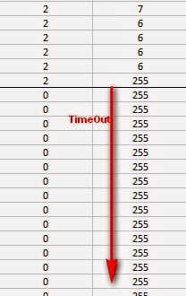
The potentiometer will be used to switch between the different LED sequences. When it reads zero, it will switch to the next sequence in the list. It will jump right back to the beginning after the last sequence. The potentiometer is also used to interact with the LEDs (e.g. controlling hue, brightness etc etc).
See the fritzing sketch below to add the potentiometer to this project.


Accelerometer connection (Y-axis)

The accelerometer makes the LEDs much more fun and interactive. We will only be using the Y-axis of the accelerometer in this sketch. By tilting the accelerometer from one side to the other, the LEDs react and respond accordingly. The accelerometer is an essential component of the digital spirit level sequence. That's right ! You can use this sketch to create your own spirit level. This digital version can also be used to measure angles !
 
Have a look below to see how to hook up the accelerometer to the Arduino. The Y-axis is connected to the Arduino analog pin 4. If you wanted to use the X and Z axis, connect them to one of the other available analog pins (eg. A3 and A5).


Let the fun begin !!

Now that you have the Arduino code uploaded to the Arduino, and have made all of the necessary wire/component connections, it is time to turn on the power supply.
 

Sequence 1: Cylon with Hue control

The LEDs will move from one end of the strip to the other. It should start off as a RED cylon effect. As you turn the potentiometer clockwise, the colour of the LEDs will change and move through the various colours of the rainbow. If the potentiometer reading gets back to zero (fully anti-clockwise), it will move to sequence 2.
 

Sequence 2: Cylon with brightness control

You will see that the LEDs have turned off. The potentiometer readings correlate with the LED brightness. At the start of this sequence, the potentiometer readings will be zero, therefore the brightness will be zero (LEDs turned off). As you turn the potentiometer clockwise, the readings increase, and so will the brightness of the LEDs.
 

Sequence 3: Comet effect with Hue and direction control

This is where the real fun begins. You control the hue of the leading LED with the potentiometer, however the LED will move along the LED strip as though it were affected by gravity. As it hits the end of the LED strip, it will bounce for a while and eventually come to a stop. The more you tilt the accelerometer, the greater the acceleration of the leading LED. The trailing LEDs have an interesting randomised glow, which creates the "comet" effect.
 

Sequence 4: FireStarter / Rainbow effect : Hue and direction control

The initial colours of LEDs in this sequence creates a fire-like animation. As the leading LED moves along the LED strip, it appears to ignite the LEDs in its path, leaving a fire trail behind it. The fire effect is best when you turn the potentiometer clockwise slightly to introduce a small amount of yellow into the mix of colours. As you turn the potentiometer further clockwise, the fire trail turns into a pretty rainbow trail. The accelerometer affects the leading LED in the same way as the previous sequence.
 

Sequence 5: Digital spirit level

This sequence was my original idea for this project, however I thought it would be nice to share some of the other cool effects I created on my journey of discovery. The idea was to make a digital version of a spirit level. I originally wanted the LEDs to represent a spirit level bubble that would "float" according to the vertical/horizontal position of the LED strip. However, as I played around with this sketch, I discovered that it could potentially be used to measure the angle of the strip relative to the horizon. The angle can be determined by the illuminated LED. If the strip is horizontal, the illuminated LEDs will be close to the middle of the strip, and their colour will be green. If the strip is vertical, the illuminated LEDs will be close to end of the strip, and their colour will be red. The colour is just an additional visual indicator.
 

Concluding Comments

The NeoPixel Digital RGB LED strip is a lot of fun. The FastLED library makes for easy programming, and allows you to get up and running really quickly. 144 LEDs on a single strip means you have plenty of room for creative algorithms and lighting effects. Add a few sensors, and "pretty" quickly turns into "awesome" !!
 
This tutorial shows you how to control a "144 NeoPixel per metre Digital RGB LED strip" with an Arduino UNO. Feel free to share your own LED creations in the comments below.


If you like this page, please do me a favour and show your appreciation :

 
Visit my ArduinoBasics Google + page.
Follow me on Twitter by looking for ScottC @ArduinoBasics.
I can also be found on Pinterest and Instagram.
Have a look at my videos on my YouTube channel.


This project would not have been possible without the collaborative effort from OpenLab.
Please visit their site for more cool projects.


However, if you do not have a google profile...
Feel free to share this page with your friends in any way you see fit.

Viewing all 112 articles
Browse latest View live